DPSIM Static Module Manual
Use this manual to build flowsheets, configure unit-operation models, run steady-state simulations and review engineering results in DPSIM Static Module.
1. Overview
DPSIM Static Module represents a mineral processing circuit as a flowsheet. The flowsheet contains equipment, called unit operations, connected by streams. Each stream carries material information such as solids flowrate, water flowrate, particle-size distribution and component content. Each unit operation applies a mathematical model to transform one or more input streams into one or more output streams.
The static simulator solves the steady-state material balance for the circuit. It does not describe how the plant changes second by second; instead, it calculates the operating point associated with the current feed data, model parameters and flowsheet connections.
2. First Launch and Project Files
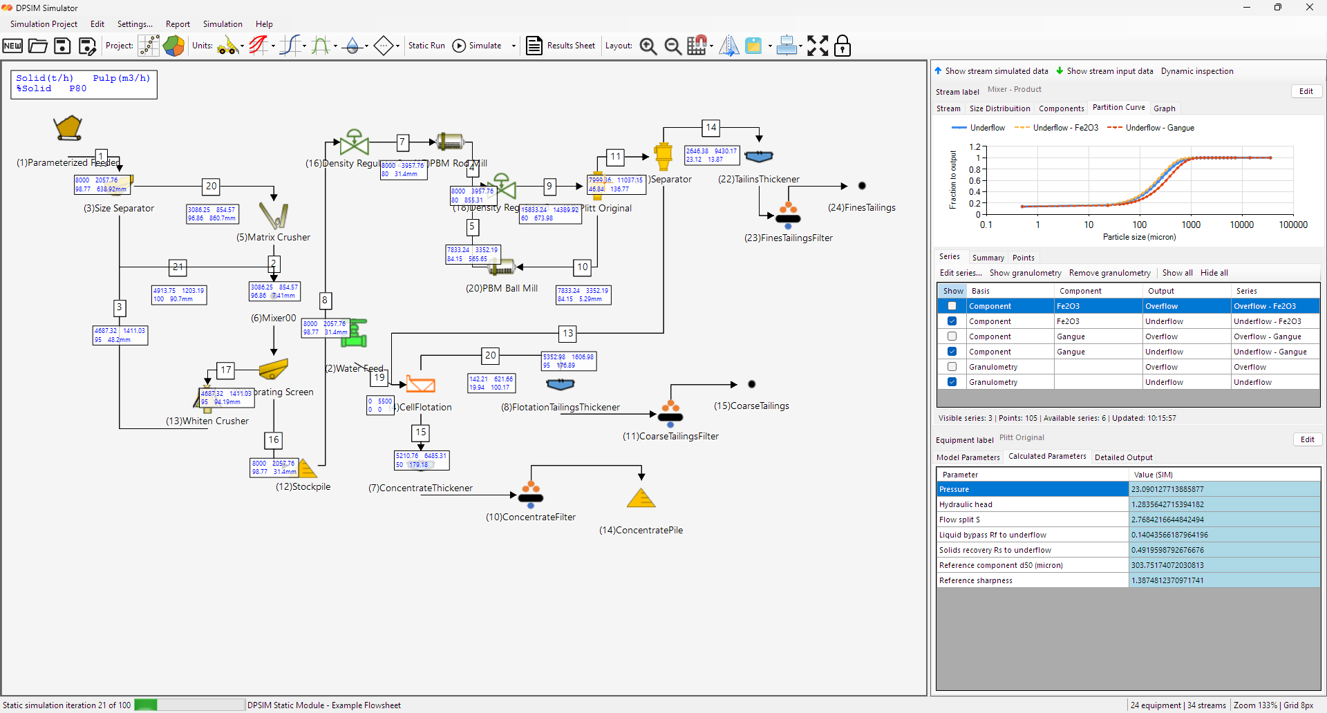
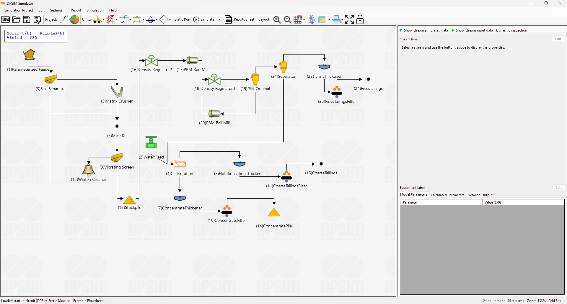
When DPSIM Static Module opens, the main workspace displays an example flowsheet with mineral processing units, streams, recycles and product streams.

Project file operations
| Command | Purpose | Typical use |
|---|---|---|
| New | Starts a new flowsheet project. | Use when beginning a new study from an empty circuit. |
| Open | Loads an existing DPSIM project or circuit file. | Use to continue a saved study or open an example circuit. |
| Save | Saves the current project. | Use frequently while building or editing a circuit. |
| Save As | Saves a copy under a new file name. | Use before creating a scenario variant. |
| Autosave | Periodically stores recovery copies according to the selected interval. | Use to reduce the risk of losing edits during model building. |
Use a clear naming convention when comparing scenarios. Keep separate files for the base case and for changes to the feed, screen or mill settings.
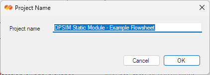
Project name
The project name appears in the workspace status and reports. Use a short, descriptive name with a case identifier such as base case, screen change, feed change or mill setting change.
3. Main Interface
The flowsheet is the main interface. Select equipment or a stream to edit or review its data in the inspector panels on the right.
Workspace areas
Important toolbar and menu commands
| Area | Command | What it does |
|---|---|---|
| Project | New, Open, Save, Save As | Manage flowsheet project files. |
| Project setup | Size distribution, Components | Edit the project particle-size mesh and component list. |
| Model palettes | Feed, Comminution, Classification, Concentration, Dewatering, Auxiliary | Add unit operations to the flowsheet. |
| Simulation | Run Static Simulation | Runs the steady-state calculation. |
| Results | Stream Results Sheet | Opens a spreadsheet-style result review window. |
| View | Zoom, grid, snap to grid, right panel, status bar | Controls how the flowsheet is displayed and edited. |
| Layout | Show labels, show flyouts, lock canvas, align tools | Controls visible stream/equipment labels and drawing layout behavior. |
Settings tabs
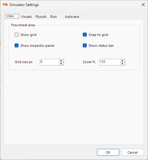
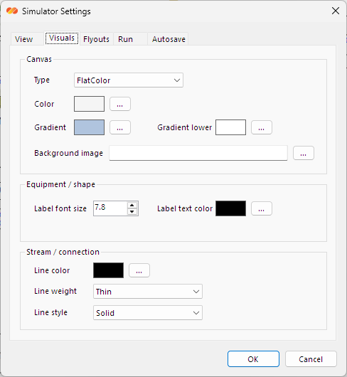
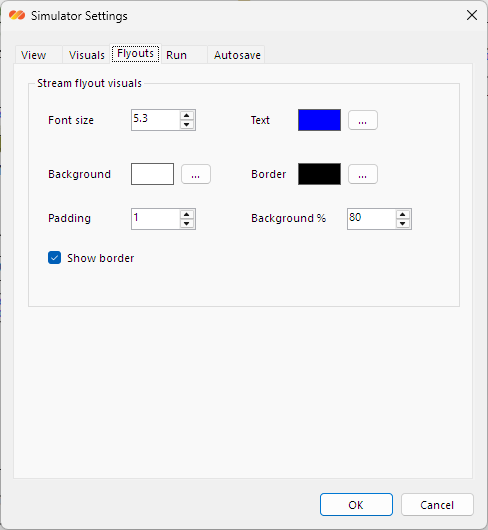
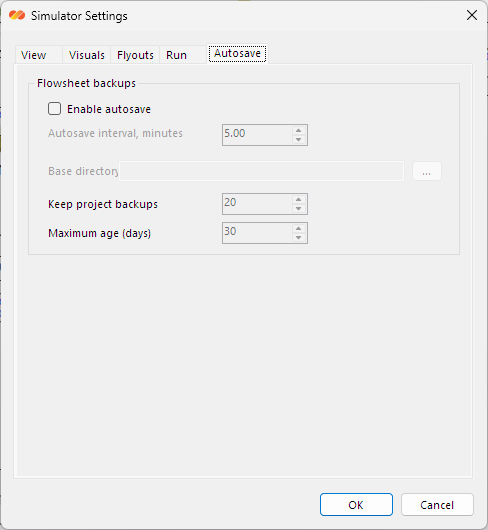
The Settings dialog contains display, flyout, run and autosave options. These options control the workspace display and static solver operation; model inputs remain in the equipment panels.
4. Project Setup
Configure the particle-size mesh and component list before entering detailed feed data or model parameters.
Particle-size mesh
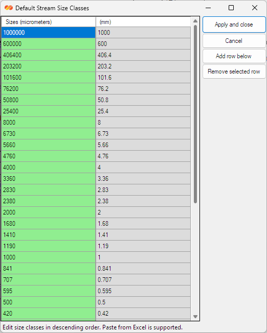
The particle-size mesh defines the size intervals used by stream granulometry and by size-dependent models. Enter the size classes in descending order and keep the final pan interval at zero. Once the mesh is set, all stream size distributions use the same interval structure.
Components
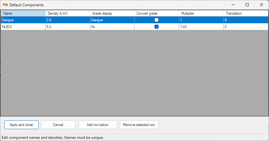
Components represent the mineral, chemical or material constituents tracked through the flowsheet. They are used for grade, assay and component-by-size calculations. Use clear names that match the plant study basis, such as Fe, SiO2, Cu, valuable mineral, gangue or other project-specific components.
| Setup item | Recommendation | Reason |
|---|---|---|
| Size intervals | Use the same mesh as laboratory or plant PSD data when possible. | Reduces interpolation and makes model calibration easier. |
| Pan interval | Keep the last interval at zero. | Represents material below the finest sieve size. |
| Component names | Use short and consistent names. | Improves readability in stream tables and reports. |
| Component order | Keep the list stable after entering data. | Avoids confusion when comparing component columns across streams. |
Practical setup sequence
- Define the project particle-size mesh.
- Define the component list.
- Add feed units and enter feed stream data.
- Add unit operations and connect streams.
- Configure model parameters.
- Run the static simulation and review results.
5. Working with the Flowsheet
The flowsheet canvas is the main workspace for building a circuit. Unit operations are added from model palettes, positioned on the canvas and connected with streams.
Adding units
Use the toolbar model categories to add equipment. The Static Module includes Feed, Comminution, Classification, Concentration, Dewatering and Auxiliary models for steady-state simulation.
| Category | Typical models | Purpose |
|---|---|---|
| Feed | Editable Product Stream Feed, Water Feed, Pulp Dilution Control, Component PSD Feeder | Introduce solids, water, size distribution and component information into the circuit. |
| Comminution | Crushers, ball mills, rod mills, vertical mills, HPGR and energy-based comminution models | Represent size reduction and associated power or product-size behavior. |
| Classification | Screens, hydrocyclones and partition models | Split material by size or component partition behavior. |
| Concentration | Flotation and component recovery models | Separate valuable and non-valuable material using grade/recovery behavior. |
| Dewatering | Static thickener and filter models | Adjust water content and solids concentration. |
| Auxiliary | Mixer, Stream Splitter, static stockpile and related support units | Combine, divide or terminate streams in the flowsheet. |
Connecting streams
Streams connect output ports to input ports. A unit may have one or more input/output ports depending on the model. When a stream is connected, it becomes part of the calculation path used by the static solver.
- Add the upstream and downstream units to the flowsheet.
- Use the available ports to create a stream connection from the upstream output to the downstream input.
- Adjust the stream path if the drawing needs a cleaner route.
- Run the static simulation and confirm that the calculated stream appears in the result panels.
Layout tools
Use zoom, grid display, snap to grid, label visibility and flyouts to keep the circuit readable. Lock the canvas during result review to prevent accidental movement of equipment or streams.
6. Streams and Material Data
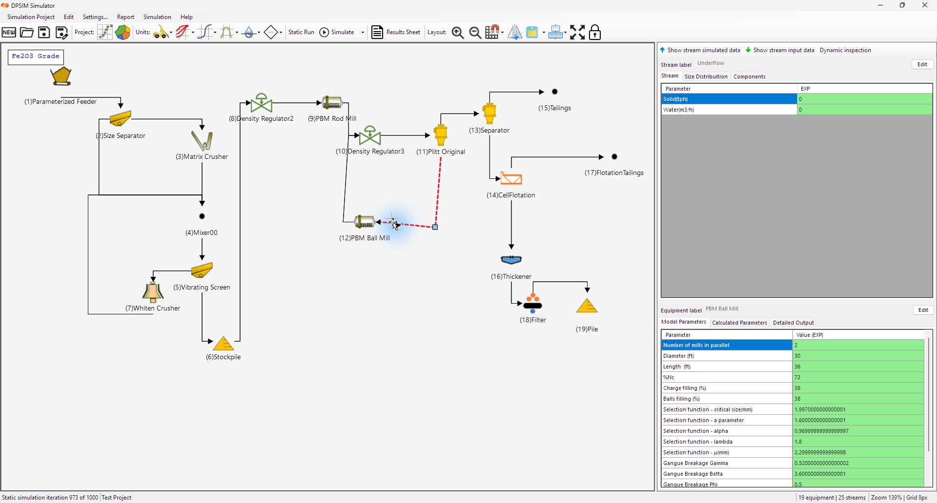
Streams carry the material state between unit operations. Feed streams usually contain user input data. Downstream streams are calculated by the simulator after a static run.
Stream properties
| Property | Description | How to use it |
|---|---|---|
| Solids flowrate | Dry solids mass flow through the stream. | Use for mass-balance checks and equipment loading. |
| Water flowrate | Water associated with the stream. | Use for water-balance review and pulp density checks. |
| Pulp/slurry flow | Total stream including solids and water. | Use when comparing hydraulic loading or slurry handling. |
| Percent solids | Solids concentration in the stream. | Use to confirm whether process streams are realistic for the equipment. |
| Particle-size distribution | Mass distribution across the project size mesh. | Use to compare feed, product and classification performance. |
| Components | Component grades or fractions, optionally by size class. | Use for grade/recovery and metallurgical balance review. |
Input data versus simulated data
Use the input data tabs to define feed streams. The simulated data tabs show calculated values after a static run. If a downstream stream has no results, check the upstream data, model parameters and stream connections.
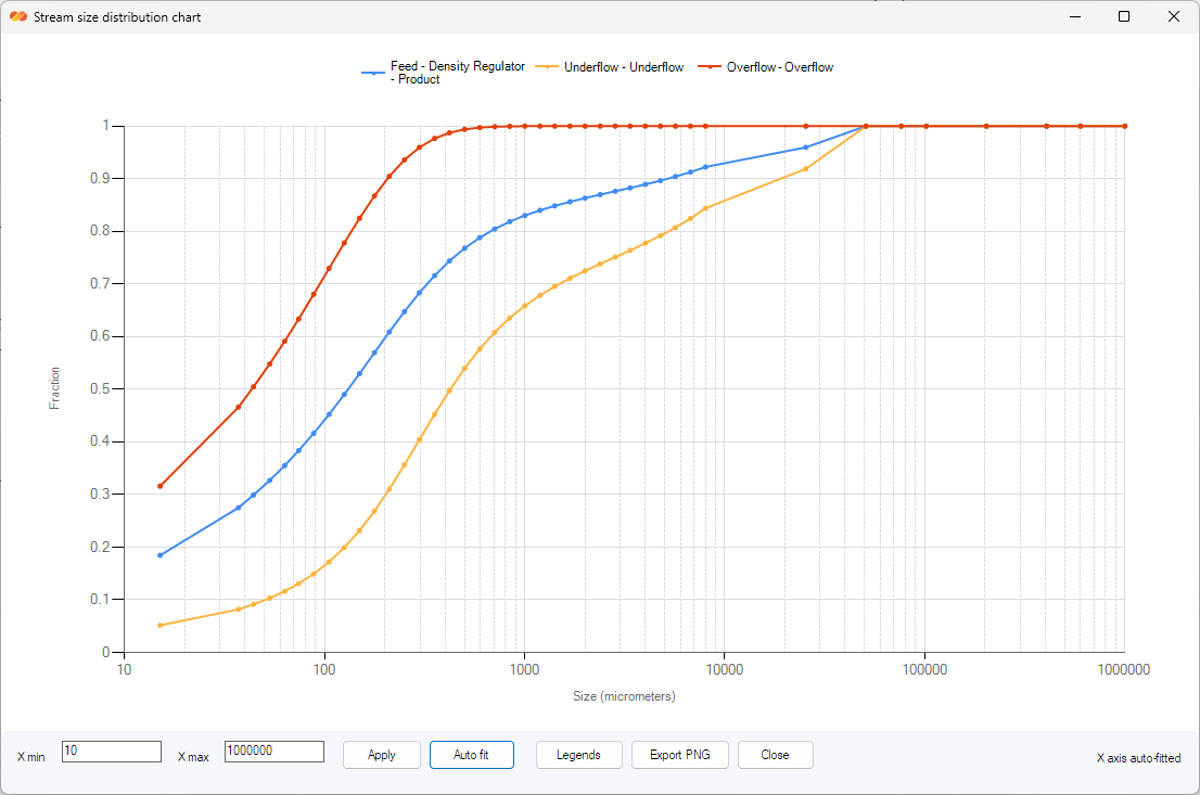
Graph views
Stream graphs help compare size-distribution curves. Use them to check whether comminution, screening, hydrocyclone or partition behavior is producing a plausible product. If a graph appears blank, verify that the stream has simulated size-distribution data and that the graph series are visible.
7. Unit Operation Models
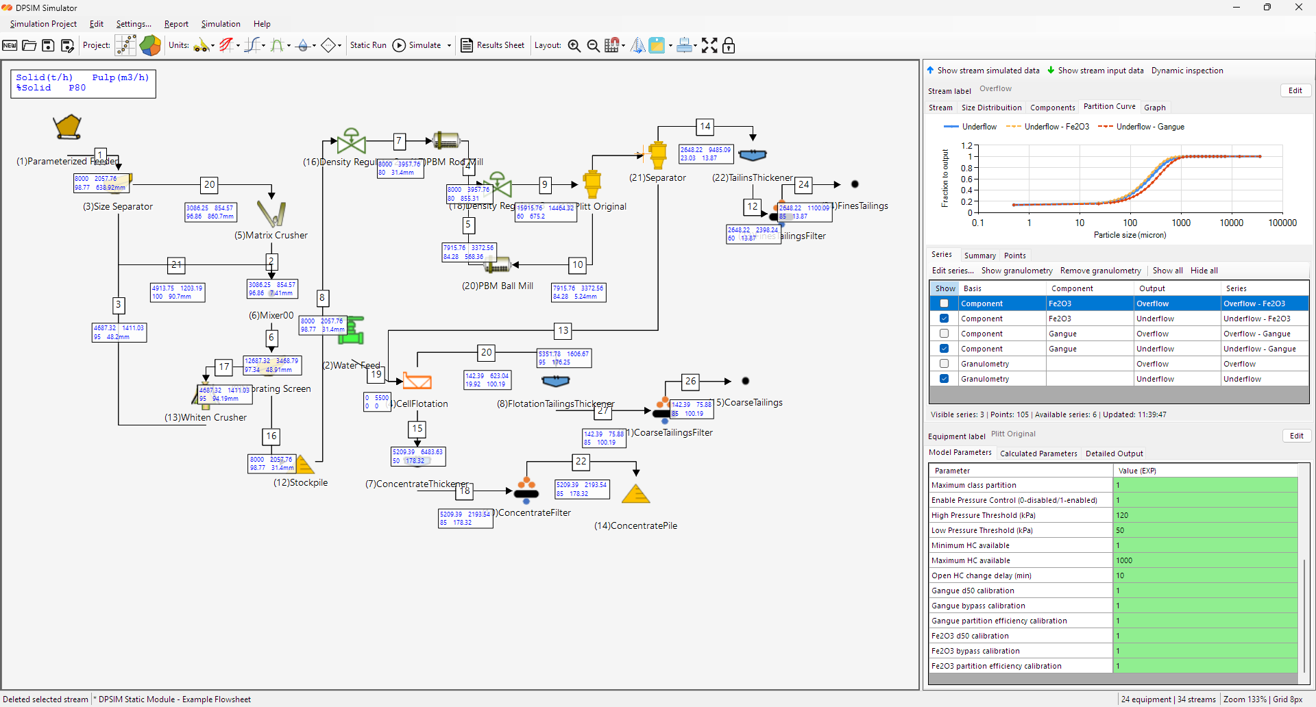
Every process unit uses a model to convert input streams into output streams. Configure and review the model in its equipment panel; equations and model-specific assumptions are documented in the DPSIM Models Reference.
Model panel tabs
| Tab or area | Purpose | Review practice |
|---|---|---|
| Model parameters | User-controlled model inputs. | Check units, default values and calibration basis before running scenarios. |
| Calculated parameters | Values derived from user inputs or the current simulation. | Use to check intermediate calculations such as power, split or capacity-related values. |
| Detailed output | Model-specific calculated tables or diagnostics. | Use when reviewing why a unit produced a particular result. |
| Reports/export tabs | Model documentation, validation and calculation details where available. | Use for engineering review or for documenting assumptions. |
Configuration examples
A comminution model typically needs parameters that describe the equipment size, operating condition, energy input or breakage behavior. A classification model typically needs parameters for cut size, efficiency or partition behavior. Auxiliary models such as mixers and splitters handle stream combination, stream division and flowsheet routing.
Check parameter definitions, equations and model-specific assumptions in the Models Reference before interpreting results.
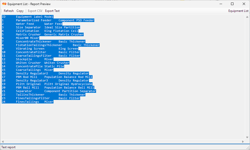
Equipment report views
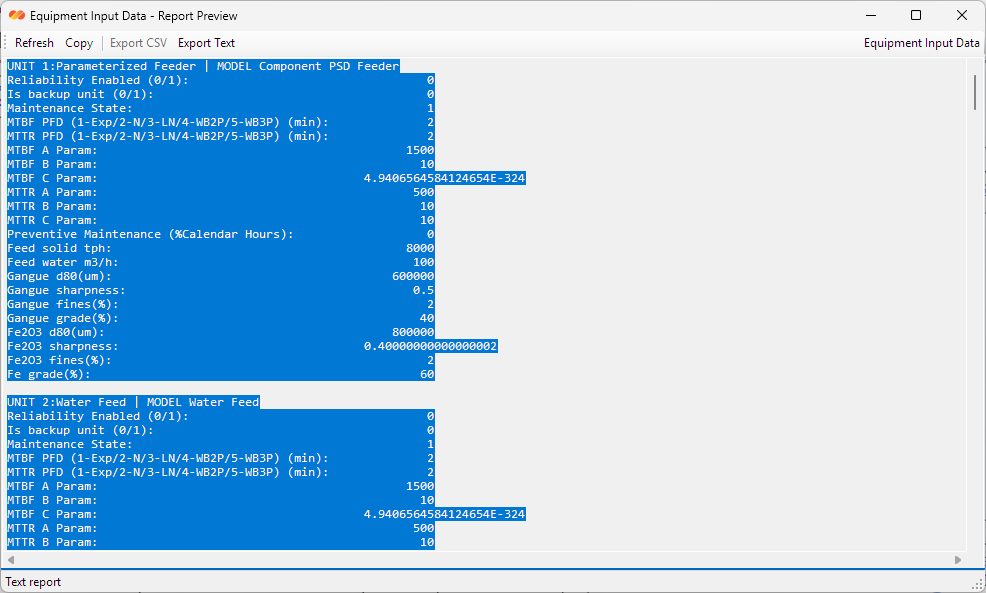
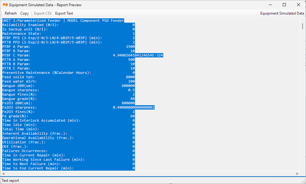
The report preview windows summarize equipment configuration and calculated values. Use them to check model setup or transfer model information to an engineering note.
8. Static Simulation Workflow
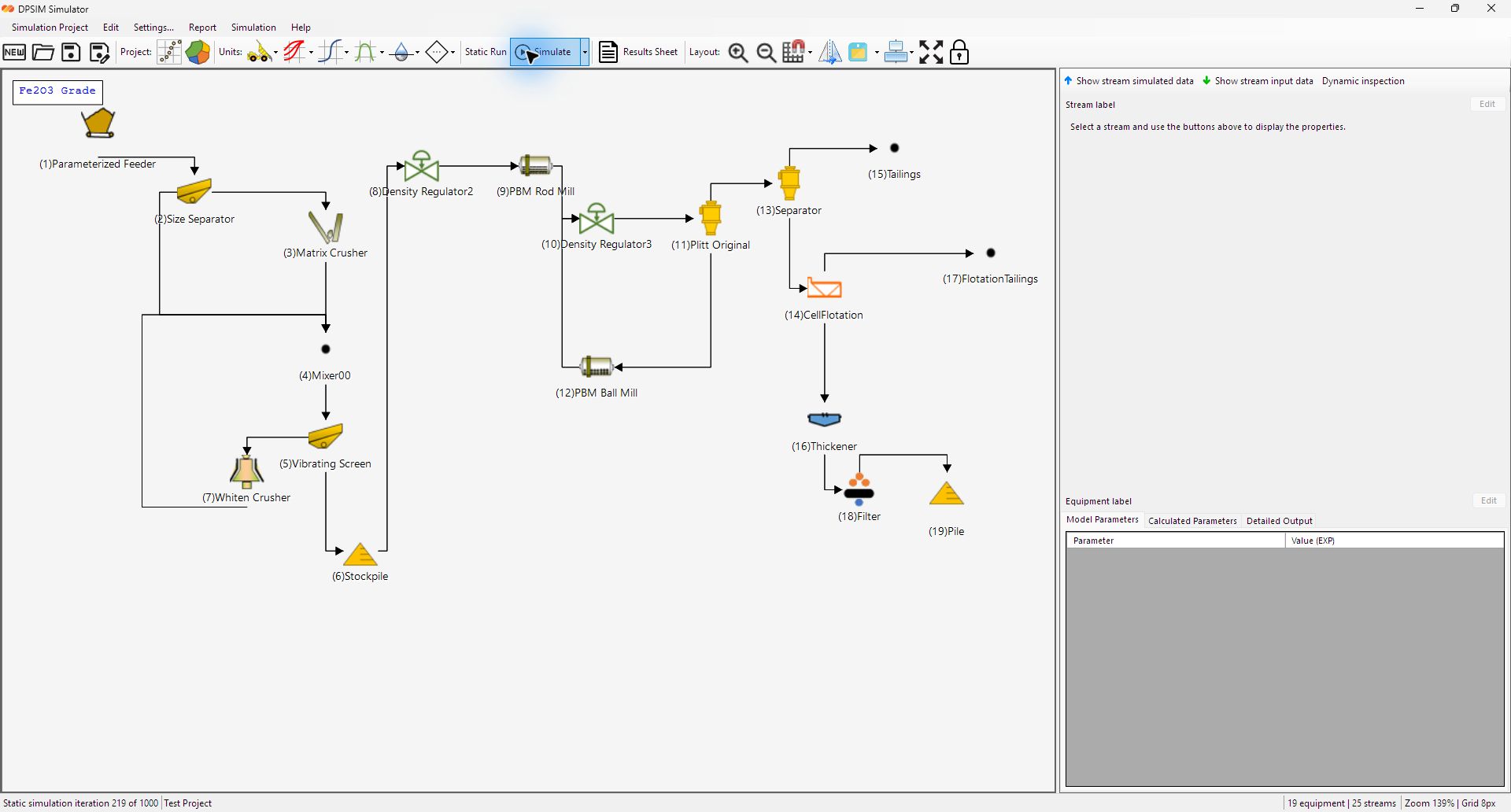
A static simulation solves the current flowsheet from the project setup, stream input data and model parameters. Start it from the toolbar or the Simulation menu.
Pre-run checklist
- The particle-size mesh and component list are defined.
- Feed streams contain solids, water, size distribution and component data as required.
- All intended equipment is connected by streams.
- Each unit operation has a suitable model and realistic parameter values.
- Recycle or split/mix structures are connected intentionally.
- Static simulation iteration count is appropriate for the circuit complexity.
Iteration settings
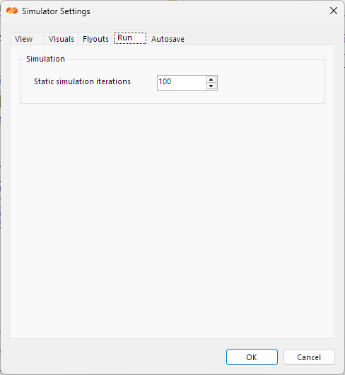
The Static Simulation Iterations setting controls how many calculation passes the solver may perform. Simple circuits may solve quickly with a small number of iterations. Circuits with recycles or stronger interdependencies may need a larger limit, such as 100 or 1000 iterations.
After the run
After a successful run, inspect the stream data, calculated equipment parameters and Results Sheet. For unexpected results, review the feed data first, followed by the connections and model parameters.
9. Results and Engineering Review
Review stream data, equipment results and the overall mass balance together. A single stream or graph is not sufficient to assess the flowsheet.
Stream Results Sheet
The Stream Results Sheet is a spreadsheet-style review window. It can load stream results, run the static simulation and load results, export CSV, copy data to the clipboard, select all, clear the grid and customize displayed lines and columns.
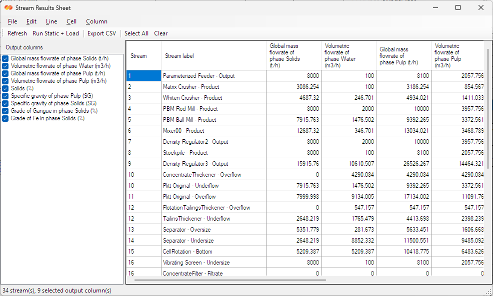
| Results Sheet feature | Use |
|---|---|
| Refresh | Reloads values from the current simulation state. |
| Run Static + Load | Runs the static simulation and then loads the updated stream values. |
| Export CSV | Exports the current grid for external review or reporting. |
| Copy to Clipboard | Copies selected result data for quick transfer into documents or spreadsheets. |
| Line tools | Add, insert, remove or load all streams as result lines. |
| Column tools | Add, insert, remove or configure output columns. |
| Stream Definition | Shows identifying information for the streams in the table. |
Engineering checks
10. Reports and Exporting
Select the report or export according to the engineering data required.
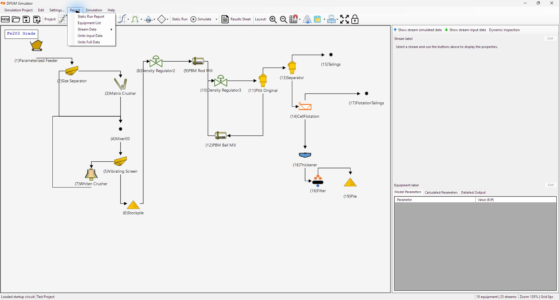
| Output | Where it is used | Typical content |
|---|---|---|
| Export Image | Project or flowsheet menu. | Flowsheet image for presentations and reports. |
| Export Stream Data | Project/report commands and Results Sheet. | Stream values, simulated data and tabular stream comparisons. |
| Export Unit Data | Project/report commands. | Equipment model parameters, calculated data and unit-level information. |
| Static Run Report | Report menu. | Markdown-style summary of the static simulation case. |
| Equipment List | Report menu. | List of unit operations in the flowsheet. |
| Equipment Input Data | Report menu. | Model input parameters and user-defined equipment settings. |
| Equipment Simulated Data | Report menu. | Calculated unit-level outputs from the latest static simulation. |
| Detailed Stream Data | Report menu. | More complete stream-by-stream data for review. |
| Global Sheet Stream Data | Report menu. | Spreadsheet-style stream data summary. |
| All Report Data | Report menu. | Combined report package containing available report sections. |
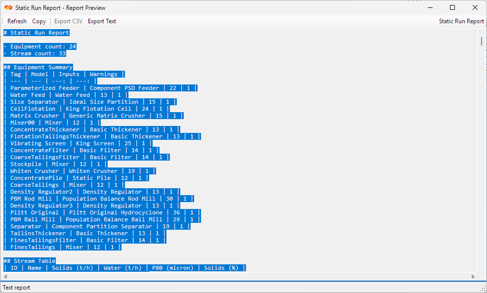
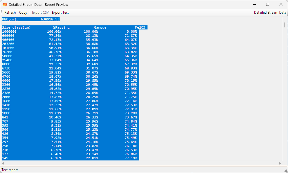
For formal engineering communication, pair exported data with a short written basis: feed assumptions, size mesh, component list, model choices, calibration notes and scenario name.
11. Example Tutorial Using the Startup Circuit
Use the startup circuit as a guided example of data flow through DPSIM. Its values are illustrative and require calibration before use in an engineering decision.
11.1 Review the flowsheet
Open DPSIM Static Module and review the complete startup flowsheet. Identify the feed units, comminution section, classification section, recirculating streams and final product streams before changing any data.
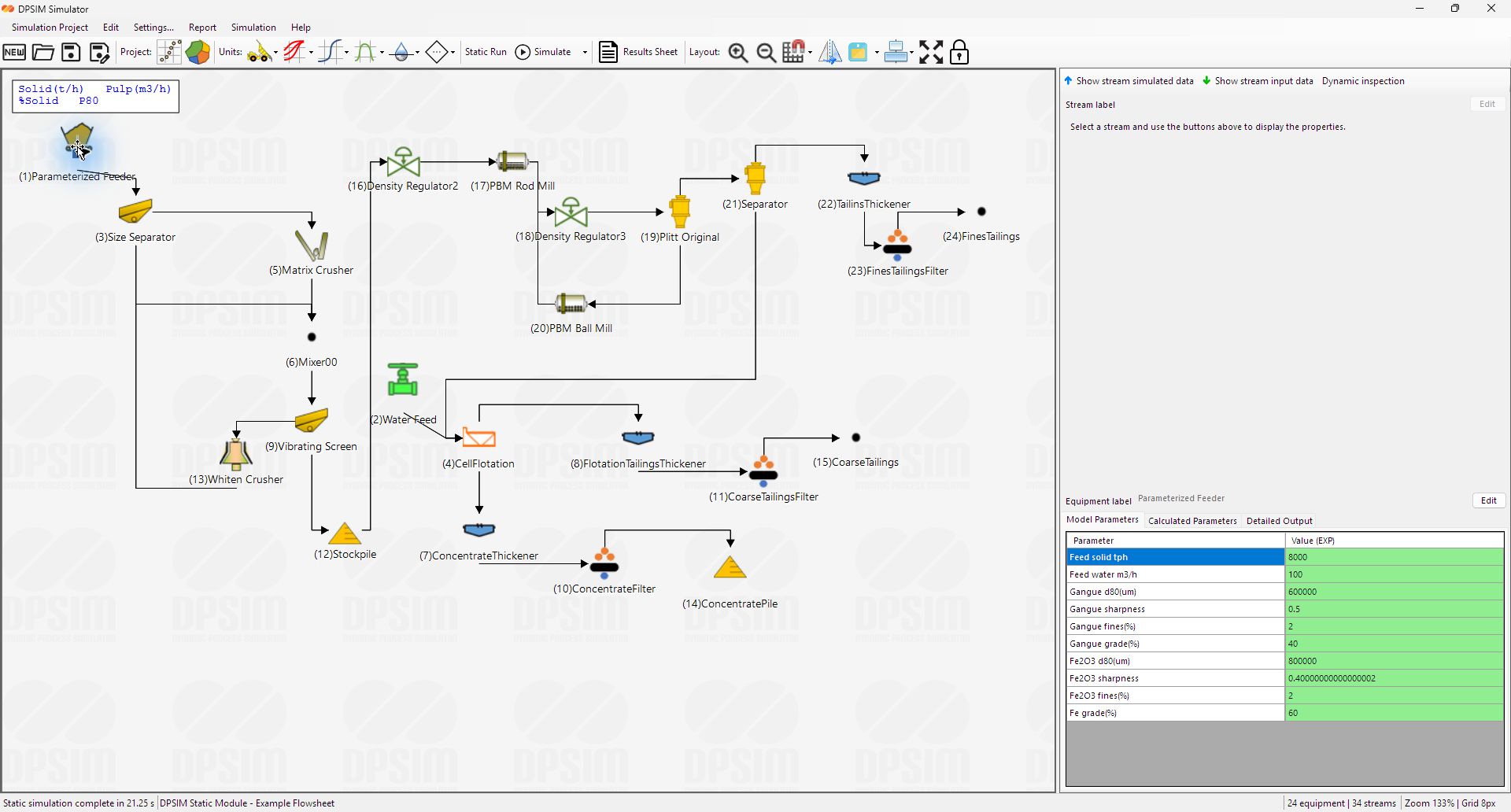
11.2 Inspect feed and equipment data
Select the Parameterized Feeder and review its solids flow, water flow and component parameters. Then inspect process equipment such as the matrix crusher, mills and Plitt hydrocyclone to understand which model parameters control each calculation.
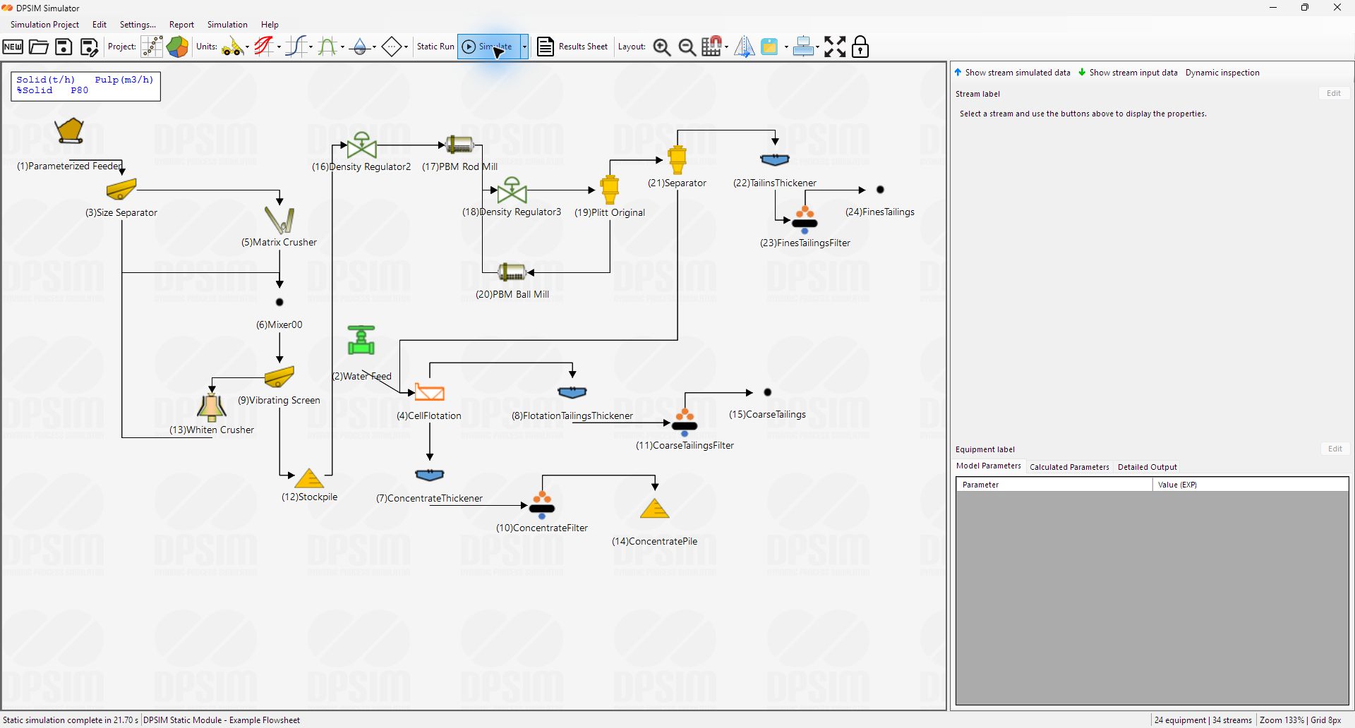
11.3 Run the static simulation
Run the static simulation and wait for the completion message in the status bar. The stream flyouts are then updated with calculated solids flow, pulp flow, percent solids and P80 values.
11.4 Compare the main streams
Open the Stream Results Sheet and load the streams required for the engineering question. Compare the main feed, circulating load, products and tailings using consistent result columns.
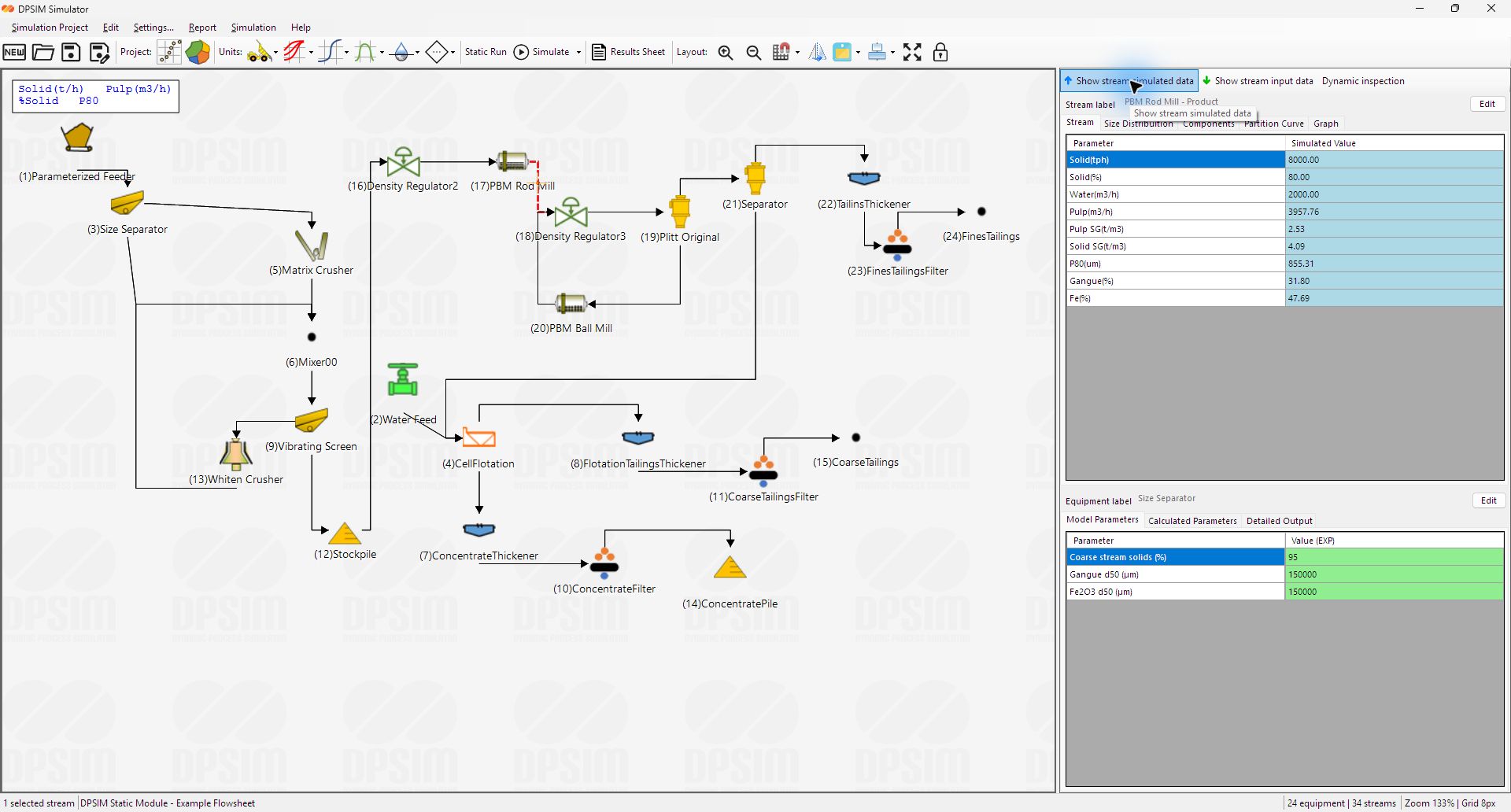
11.5 Review stream detail and particle size behavior
Select a stream on the flowsheet to inspect its calculated values. Use the Size Distribution and Graph views to compare feed, circulating and product streams and check whether the results are plausible for the example.
Save a copy of the project before changing parameters for scenario comparison.
After the walkthrough, change one operating parameter at a time, rerun the static simulation and compare the Results Sheet to observe its effect on the circuit balance.
12. Troubleshooting and Best Practices
| Symptom | Likely cause | Action |
|---|---|---|
| No result appears for a stream. | The stream is not connected, the upstream unit has missing data, or the simulation has not been run. | Check connections, feed data and model parameters, then rerun the static simulation. |
| Size-distribution graph is blank. | The stream has no simulated granulometry or graph series visibility is not enabled. | Select the relevant stream, confirm simulated size data exists and review graph series settings. |
| Results look physically unrealistic. | Feed data, water data, component data or model parameters may be inconsistent. | Start from feed streams and work downstream, checking one unit at a time. |
| Circuit is hard to read. | Equipment and streams are not aligned or labels/flyouts are cluttered. | Use grid, snap to grid, zoom, label visibility and alignment tools. |
| Changing project mesh caused data loss. | Project mesh changes affect all streams. | Set mesh before detailed data entry and save a backup before changing it. |
| Simulation does not stabilize as expected. | Recycle structure or model settings may require more iterations or better initial data. | Increase static iteration count and inspect recycle-connected units for unrealistic parameters. |
Best practices
- Keep project files organized by scenario.
- Use clear stream and equipment names.
- Document assumptions outside the model when preparing engineering deliverables.
- Review both stream-level and unit-level results.
- Use the Models Reference whenever a parameter meaning is not obvious.
13. Static Module Boundaries
DPSIM Static Module supports flowsheet building, stream definition, unit-operation model configuration, static simulation, result review and data export.
DPSIM Full adds dynamic simulation, process control, reliability analysis, maintenance events and time-based plant behavior. Contact EPM for project applications that require these capabilities.