Before adding a feed or process equipment, DPSIM needs to know what the solid material is made of.
This is done by defining the project components.
A component represents a constituent of the solid phase that DPSIM will track throughout the flowsheet. Depending on the application, components may represent minerals, chemical constituents or other solid fractions relevant to the process.
Examples include:
- hematite;
- quartz;
- magnetite;
- valuable mineral;
- gangue;
- Fe₂O₃;
- SiO₂;
- Al₂O₃.
Once defined, these components are available throughout the entire simulation and can later be assigned different proportions in each stream and particle size class.
What is a component in DPSIM?
A mineral processing stream contains more information than simply a total mass flow.
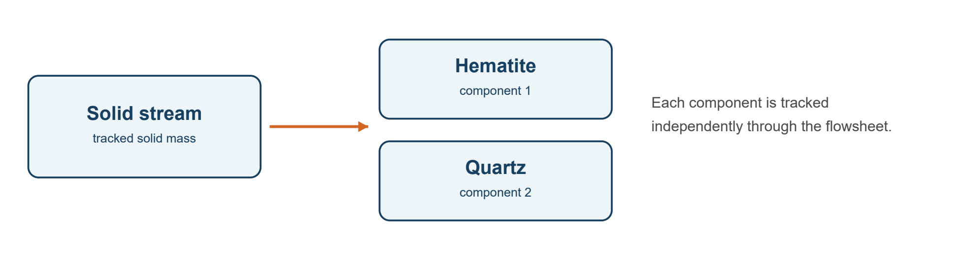
Consider an iron ore feed containing hematite and quartz.
A simplified representation could be:
Solid stream = Hematite + Quartz
DPSIM can track the mass associated with each component as the material passes through crushers, screens, hydrocyclones, separators and other process units.
This makes it possible to calculate quantities such as:
- component grades;
- component mass flowrates;
- component recoveries;
- concentrate and tailings composition;
- component distribution by particle size;
- solid density.
The component definition therefore establishes the composition basis of the entire simulation.
Water does not need to be created as a solid component.
DPSIM tracks water separately from the solid components, allowing slurry properties such as percent solids and volumetric flow to be calculated independently.
Opening the Components editor
In the DPSIM toolbar, select:
Set Components
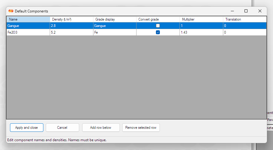
This opens the Default Components window.

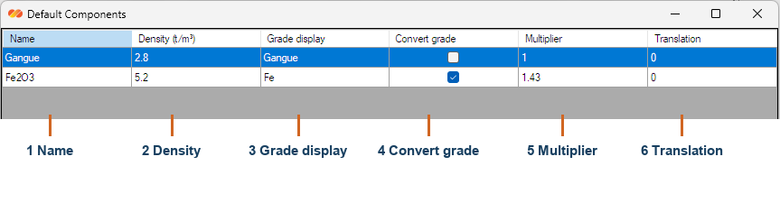
The component table contains the following fields:
Name
The identifier used for the component throughout the project.
Density (t/m³)
The density assigned to the solid component.
Grade display
The name that DPSIM can use when presenting the component grade.
Convert grade
Enables an optional conversion between the internally tracked component and the grade displayed to the user.
Multiplier
Conversion factor used when grade conversion is enabled.
Translation
Optional translation term used in the grade conversion.
For most basic simulations, only Name and Density need particular attention.
The grade conversion fields become useful when the quantity reported by the laboratory or plant is different from the component used internally in the simulation.
Adding components
Use:
Add row below
to create another component.

For a simple example, consider a material represented by two mineral components:
| Name | Density |
|---|---|
| Hematite | 5.2 t/m³ |
| Quartz | 2.65 t/m³ |
The exact component structure should reflect the objective of the simulation.
If the study is concerned only with the separation between valuable and non-valuable material, a simplified structure such as:
Valuable Mineral
Gangue
may be sufficient.
If the process needs to track several constituents independently, more components can be created.
For example:
Fe₂O₃
SiO₂
Al₂O₃
Other

The important point is that a component should represent something that needs to be tracked independently through the flowsheet.
Choosing the appropriate level of detail
It is tempting to define every chemical constituent available in the assay.
That is not always necessary.
The component structure should be detailed enough to answer the engineering question being studied, but not more detailed than the available data can support.
For example, if the objective is simply to evaluate a silica rejection stage, a model containing:
Iron-bearing material
and
Silica-bearing material
may sometimes be sufficient.
A more detailed study may instead require:
Hematite
Goethite
Quartz
Kaolinite
and other relevant minerals.
The best component definition therefore depends on both:
- the objective of the simulation;
- the information available to describe the ore.
Engineering note
Adding more components does not automatically make a model more accurate.
Every additional component requires meaningful information about its distribution in the feed and, depending on the process model, its behavior through the equipment.
A simpler representation supported by good data is generally more useful than a highly detailed representation based on assumptions.
Why component density matters
Each component in DPSIM has its own solid density.
This is not simply descriptive information.
DPSIM uses the component masses and their respective densities to calculate the overall solid specific gravity of a stream.
Conceptually, the total solid volume is obtained from the volume occupied by each component:
Component volume = Component mass / Component density
The stream solid density can then be obtained from:
Solid density = Total solid mass / Total solid volume
This means that the calculated solid density can change as the composition of a stream changes.
For example, if a separation process produces one stream richer in a high-density mineral and another richer in a low-density gangue mineral, their calculated solid densities can also be different.
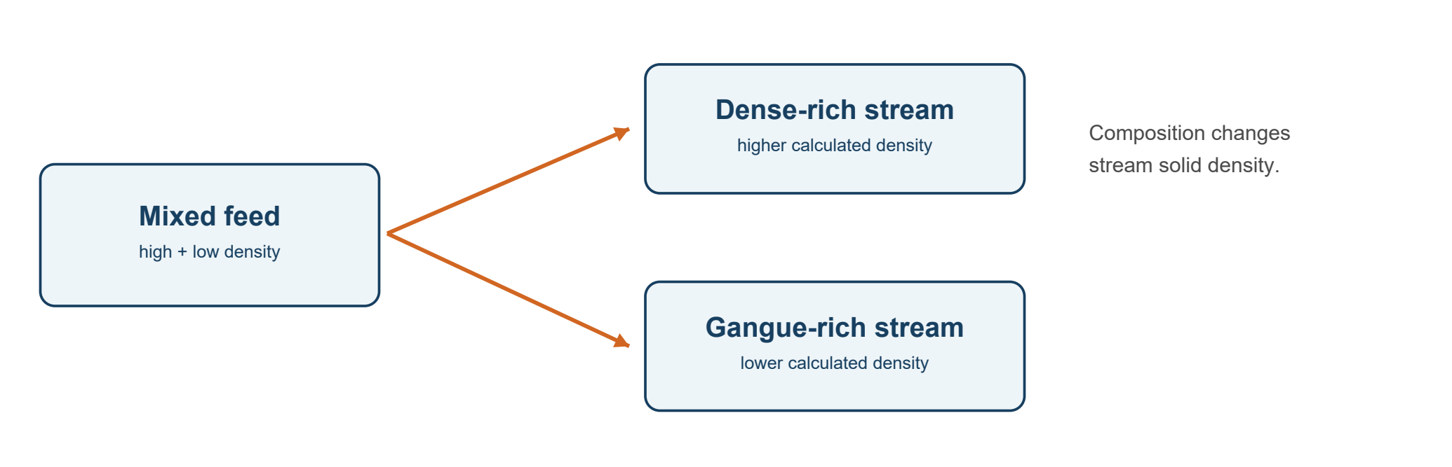
This becomes particularly important in processes where density influences equipment behavior or slurry calculations.
Component name and grade are different concepts
The component definition tells DPSIM what material is being tracked.
The grade tells DPSIM how much of that component is present in a particular stream.
These are different stages of the simulation setup.
For example, defining:
Hematite
and
Quartz
does not yet specify whether the feed contains 20%, 50% or 80% hematite.
At this stage, we are only defining the possible constituents of the solid material.
The actual feed composition will be entered later when we configure the feed.
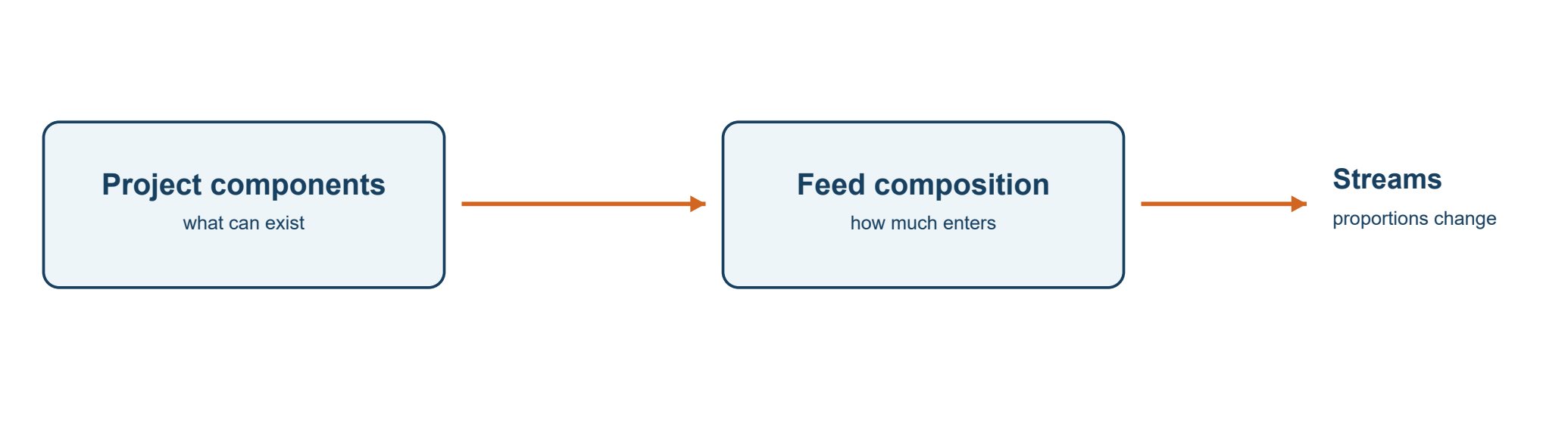
This distinction is important because the same component definitions are shared by the complete project, while their proportions can change from stream to stream as the material passes through the process.
Grade display and grade conversion
Sometimes the component used internally in the mass balance is not the quantity normally reported as the process grade.
A common example is an oxide represented as a mineral or chemical component while the plant reports the grade as the corresponding element.
DPSIM provides an optional grade display conversion for this purpose.
The relationship used is:
Canonical grade = Display grade × Multiplier + Translation
and therefore:
Display grade = (Canonical grade − Translation) / Multiplier
For example, DPSIM contains a predefined behavior for a component named:
Fe2O3
When this component is used, the grade can be displayed as:
Fe
with the appropriate conversion factor.

This allows the internal mass balance to remain based on the selected component while results can be presented using the grade convention normally used in the project.
For simulations that do not require this distinction, leave grade conversion disabled.
Naming components
Component names should be simple, clear and consistent.
Good examples include:
Fe2O3
SiO2
Hematite
Quartz
Magnetite
Gangue
Avoid creating two components with different spelling that represent the same material, such as:
Silica
and
SiO2
unless they intentionally represent different quantities in the model.
DPSIM requires component names to be unique.
Consistent naming becomes increasingly important as the flowsheet grows because component names appear in stream results, model parameters and component-by-size calculations.
Applying the component definition
After defining the components, select:
Apply and close

The component list becomes part of the project definition.
DPSIM requires at least one component to remain in the project, and each component must have:
- a unique name;
- a positive numeric density.
Once the component structure has been established, save the project.
At this point, DPSIM knows what types of solid material can exist in the simulation, but it still does not know how those solids are distributed by particle size.
That is our next step.
From composition to particle size
Mineral processing behavior depends strongly on both composition and particle size.
Two streams may contain exactly the same total amounts of hematite and quartz while behaving very differently if their particle size distributions are different.
DPSIM therefore represents the solid material using both dimensions:
Component
and
Particle size
Later, these concepts will be combined so that the simulator can represent quantities such as:
Hematite in the 150–106 µm fraction
or:
Quartz in the 45–38 µm fraction
This component-by-size representation is one of the foundations of mineral processing simulation.
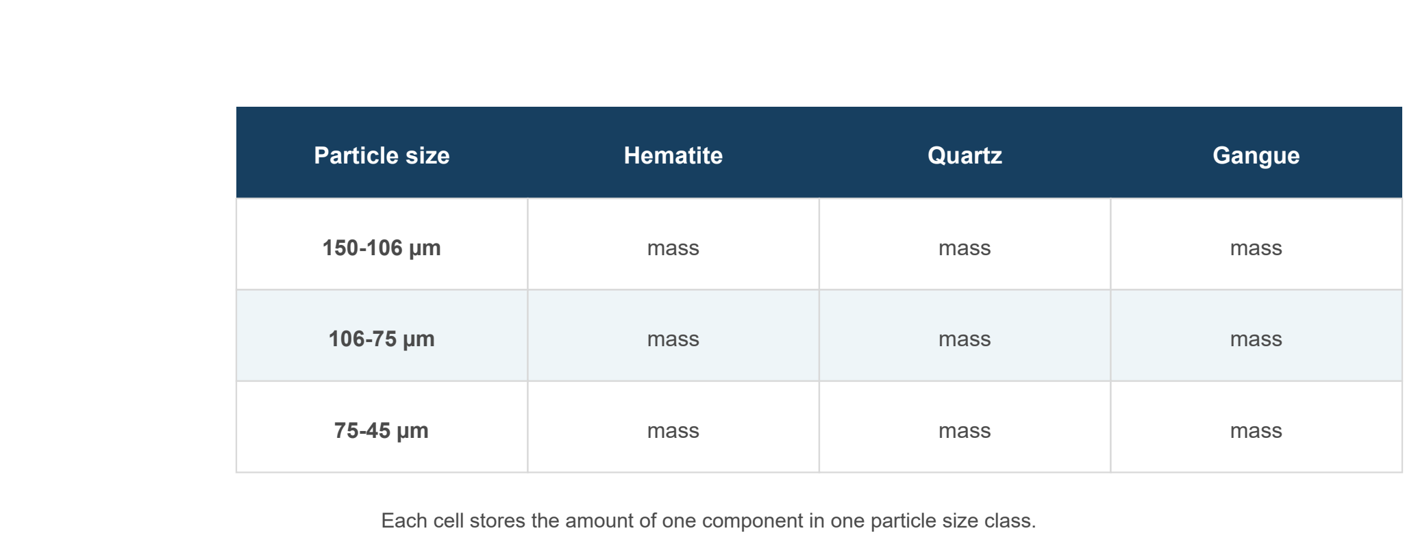
Before entering those distributions, however, we first need to define which particle size classes will exist in the project.
The next tutorial will show how to configure the Particle Size Distribution mesh in DPSIM, including an important convention used internally by the simulator:
particle sizes are stored from largest to smallest.