DPSIM is a process simulation environment designed for mineral processing flowsheets.
The Static Module is focused on steady-state simulation: the flowsheet is represented by interconnected process units, and the simulator calculates the material streams according to the selected models, operating parameters and feed characteristics.
This tutorial introduces the DPSIM workspace and the basic project workflow. We will not configure minerals, particle size distributions or process models yet. The objective is simply to become familiar with the environment and prepare a new simulation project.
In this tutorial you will learn how to:
identify the main areas of the DPSIM interface;
create a new simulation project;
understand the flowsheet workspace;
use basic visualization tools;
name your project;
save and reopen a DPSIM simulation.
What is the DPSIM Static Module?
Mineral processing plants can be represented as a network of unit operations connected by material streams.
A feed enters the flowsheet, passes through equipment such as crushers, mills, screens, hydrocyclones, flotation cells, magnetic separators or dewatering equipment, and eventually leaves the circuit as one or more products.
In DPSIM, this process is reproduced using mathematical models.
The Static Module calculates the flowsheet under steady-state conditions. Instead of following changes through time, the objective is to determine the operating condition that results from a defined feed, flowsheet configuration and set of model parameters.
This makes static simulation particularly useful for tasks such as:
developing and evaluating process flowsheets;
performing mass and water balances;
predicting particle size distributions;
tracking solid components through the process;
evaluating grade and recovery;
comparing equipment models or operating conditions;
studying recycle circuits and circulating loads.
A flowsheet simulator does not replace engineering judgment. Its predictions depend on how well the selected models and parameters represent the process being studied.
Engineering note
A mineral processing simulation is more than a graphical flowsheet. Three elements ultimately define the calculation:
Material → Flowsheet → Models
The material describes what enters the process.
The flowsheet defines where the material goes.
The models define what happens to it inside each unit operation.
We will build these three elements progressively throughout this tutorial series.
Exploring the DPSIM interface
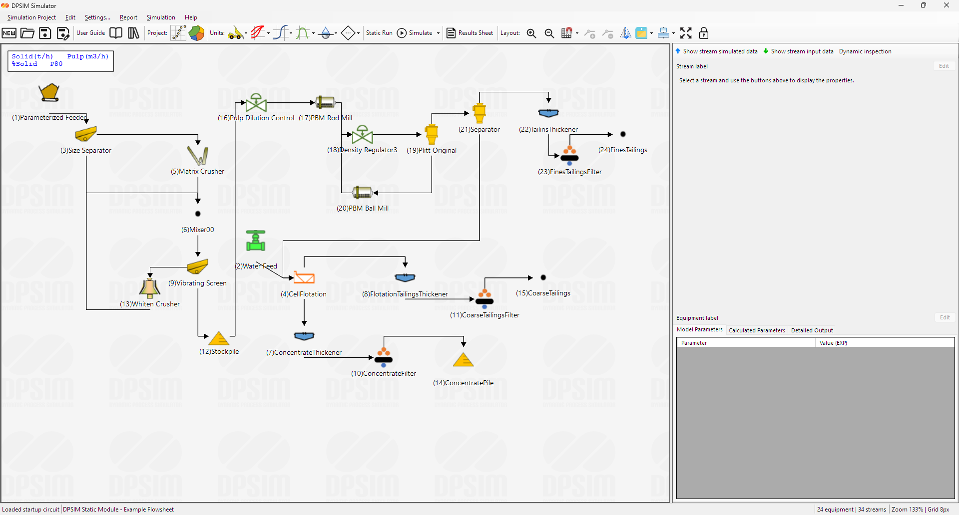
When the DPSIM Static Module is opened, the main window provides the tools required to build, configure and simulate a mineral processing flowsheet.
The central area is the flowsheet canvas.
This is where process equipment will be positioned and connected by streams. As the simulation becomes more complex, the canvas becomes the graphical representation of the complete process circuit.
Above the canvas are the main menus and toolbars used to work with the project, add process models, run calculations and access results.
The Simulation Project menu contains the main project commands, including:
New
Open
Project Name
Save
Save As
Other menus provide access to editing, interface settings, reports and simulation functions.
Depending on the selected interface configuration, DPSIM can also display an Inspector Panel beside the flowsheet. This area is used to inspect information associated with elements selected in the simulation.
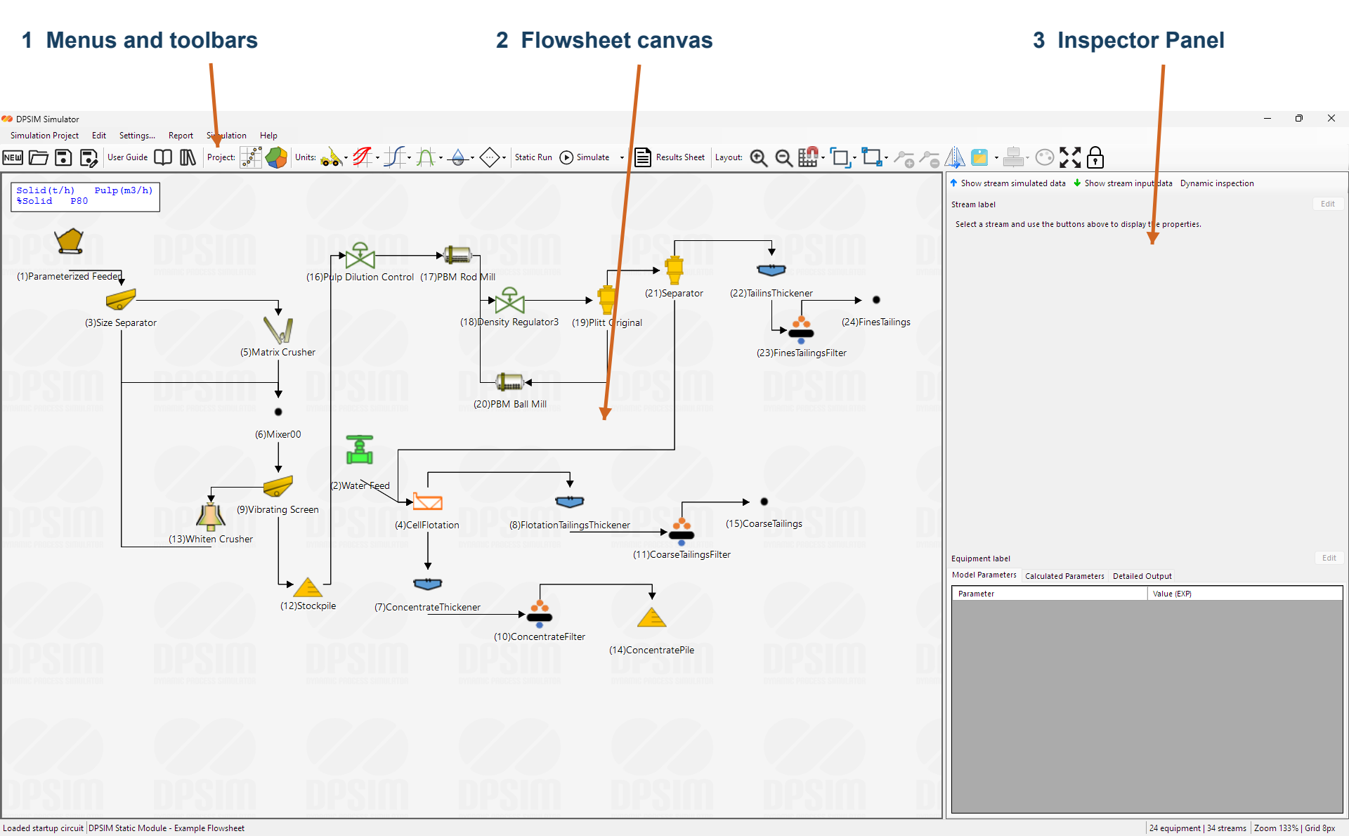
At this stage, you do not need to understand every button.
The most important area is the flowsheet canvas. Most of the simulation workflow will happen by adding equipment to this area, connecting the units and editing their properties.
Creating a new simulation project
To start with an empty project, select:
Simulation Project → New
or use:
Ctrl + N
This initializes a new DPSIM simulation project.
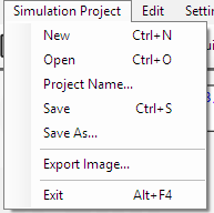
A project will eventually contain much more than the graphical arrangement shown on the screen. It will include the material definition, process units, streams, equipment models, model parameters and simulation data required to reproduce the flowsheet.
For this reason, it is good practice to treat each DPSIM file as a complete simulation study rather than simply as a drawing.
Before adding equipment, give the project a meaningful name.
Go to:
Simulation Project → Project Name…
For example:
Iron Ore Beneficiation – Tutorial
or:
Grinding Circuit – Base Case
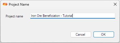
Meaningful project names become particularly useful when several alternatives, cases or operating scenarios are created later in a study.
Understanding the flowsheet workspace
The large central canvas is where the process will be constructed.
Process equipment is represented by graphical objects, while material transfer between units is represented by streams.
Conceptually, the final structure will look like:
Feed → Process Unit → Process Unit → Product
More complex circuits can include branches, multiple products and recycle streams.
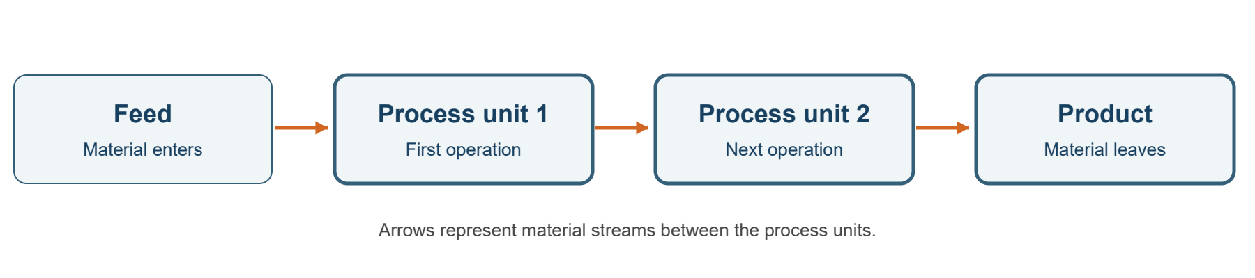
The flowsheet is not only a process diagram.
Each equipment object is linked to a mathematical model, and each stream carries calculated information about the material moving between process units.
As the tutorial series progresses, these streams will contain information such as:
solids flowrate;
water flowrate;
percent solids;
solid and pulp density;
particle size distribution;
component grades;
component distribution by particle size;
P80 and other calculated properties.
This connection between the graphical flowsheet and the underlying material calculations is the core of DPSIM.
Working with the canvas
Before creating a large flowsheet, it is useful to become familiar with a few workspace controls.
DPSIM provides options such as:
Show Grid
Displays a reference grid on the flowsheet canvas.
Snap To Grid
Aligns objects to the grid while they are being positioned.
Show Inspector Panel
Displays or hides the side panel used to inspect elements of the simulation.
Show Status Bar
Displays or hides the status information at the bottom of the interface.
Zoom controls are also available when working with larger flowsheets.
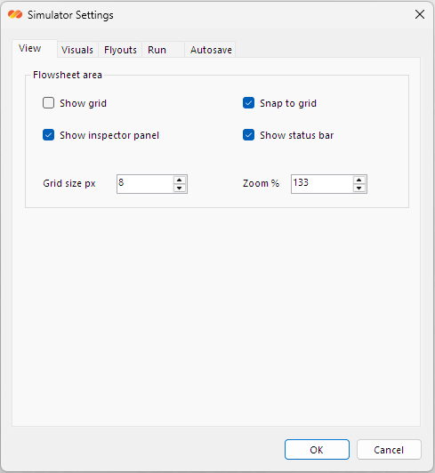
Using the grid and snap functions is optional, but they can help maintain a clean flowsheet layout, especially when the model contains many units and recycle streams.
A clear flowsheet is not only visually better. It also makes process connectivity easier to verify and reduces the chance of misunderstanding the circuit when the simulation is reviewed later.
Saving the simulation
Even though the project is still almost empty, save it before continuing.
Select:
Simulation Project → Save
or use:
Ctrl + S
For a project that has not yet been saved, DPSIM will allow you to define its file location.
You can also use:
Simulation Project → Save As…
when you want to create a separate copy.
Saving separate files is useful when developing alternative process configurations.
For example:
Grinding_BaseCase
Grinding_HigherThroughput
Grinding_AlternativeCyclone
This preserves the original simulation while allowing different cases to evolve independently.
Reopening an existing project
To continue working with a previously saved simulation, select:
Simulation Project → Open
or:
Ctrl + O
Select the desired DPSIM project file and open it.

When working on engineering studies, it is good practice to save important milestones rather than continually replacing the same file.
A simple naming strategy can make comparisons much easier later:
Project_Base
Project_Case_A
Project_Case_B
Project_Final
The objective is not to create unnecessary copies, but to preserve the important stages of the simulation development.
What we have established
At this point, we have not simulated any mineral processing operation yet.
That is intentional.
Before constructing a flowsheet, it is important to understand the hierarchy of information that DPSIM will use.
We now have the first element:
Simulation Project
Next, we need to describe the material that will move through that project.
In mineral processing, this requires more than defining a total mass flow. The solid phase may contain several components with different grades, densities and behavior throughout the process.
The next tutorial will introduce Components and show how DPSIM represents the constituents of the solid phase before we define its particle size distribution.