Particle size is one of the fundamental variables in mineral processing.
Crushing and grinding change particle size. Screens and hydrocyclones separate particles according to size. Flotation, gravity separation and other concentration processes may also respond differently across the particle size range.
Before DPSIM can represent these effects, the project needs a common particle size mesh.
In this tutorial, we will define the size classes that will be used throughout the simulation.
In this tutorial you will learn how to:
- understand the difference between a size mesh and a particle size distribution;
- open the Default Stream Size Classes editor;
- define the particle size boundaries used by the project;
- understand the descending size convention used by DPSIM;
- add, remove and paste size classes;
- choose an appropriate level of size resolution.
Size mesh and particle size distribution are not the same thing
Before entering any values, it is important to distinguish two concepts.
The size mesh defines the particle size classes available in the simulation.
The particle size distribution, or PSD, describes how much material is present in each of those classes.
For example, a project could use the following size boundaries:
1000 µm
500 µm
250 µm
125 µm
63 µm
38 µm
These values define the framework in which particle size distributions will later be represented.
They do not yet tell DPSIM how much material is present at each size.
A feed, crusher product and screen undersize may all have completely different particle size distributions while using exactly the same project size mesh.
This common mesh allows material to move consistently between different unit operations.
Why mineral processing models use size classes
A real mineral processing stream contains an enormous number of individual particles.
Representing every particle separately would be impractical.
Instead, DPSIM divides the particle population into discrete size classes and calculates the amount of material associated with each class.
Conceptually:
Coarse particles
↓
Intermediate particles
↓
Fine particles
The narrower the classes, the more detail is available to describe the particle population.
However, increasing the number of classes also increases the amount of data and calculation required by the simulation.
This discretized representation is particularly important for models such as:
- crushers;
- grinding mills;
- screens;
- hydrocyclones;
- size-dependent separators;
- component-by-size calculations.
Opening the size class editor
In the DPSIM toolbar, select:
Set default sieves openings
This opens the:
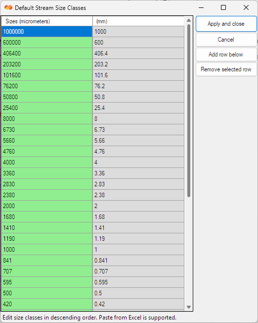
Default Stream Size Classes
window.
The editor contains two columns:
Sizes (micrometers)
The editable project size values in µm.
(mm)
The same values automatically displayed in millimeters for convenience.
The micrometer column is the editable definition used by the project.
For example:
1000 µm = 1 mm
250 µm = 0.25 mm
38 µm = 0.038 mm
The millimeter column helps when the same flowsheet contains both coarse and fine particle sizes.
DPSIM uses descending particle size order
This is an important DPSIM convention.
The project size classes must always be entered in descending order:
largest size → smallest size
For example:
| Size |
|---|
| 1000 µm |
| 500 µm |
| 250 µm |
| 125 µm |
| 63 µm |
| 38 µm |
and not:
38 → 63 → 125 → 250 → 500 → 1000 µm
DPSIM validates this order when the mesh is edited.
If a lower row contains a size larger than the row above it, the editor will indicate:
Please enter values in descending order.
This ordering is not simply a visual preference. The same index order is used internally by DPSIM when storing particle size distributions and component-by-size information.
DPSIM Tip
Whenever particle size vectors are created externally for DPSIM, remember:
SizeDistribution = descending order
Keeping this convention consistent prevents the PSD from being associated with the wrong size classes.
Understanding the top size and pan
DPSIM treats the size distribution as a sequence of classes from the coarse end to the fine end.
The first position represents the top-size boundary.
The final position is treated as the pan, representing the finest material below the last effective sieve interval.
When a stream particle size distribution is later entered, DPSIM preserves this structure:
Top size first
↓
Intermediate size fractions
↓
Pan last
The top-size fraction is handled as the upper boundary of the distribution, while the pan completes the retained-size balance at the fine end.
This convention will become clearer when we enter an actual feed PSD in the next tutorial.
Adding and removing size classes
To increase the resolution of the size mesh, select a row and use:
Add row below
A new size class will be inserted below the selected row.
Enter the desired particle size and maintain the descending order.
To remove a class, select the corresponding row and use:
Remove selected row
The top-size row is protected because it defines the upper boundary of the particle size structure.
When modifying the mesh, think about the size range that will actually be relevant to the process.
A crushing circuit may require a wide range extending from hundreds of millimeters to a few millimeters.
A grinding and flotation circuit may require much finer classes extending into the micrometer range.
Pasting a size mesh from Excel
For projects containing many size classes, entering each value manually would be inefficient.
The DPSIM size editor supports pasting a size list directly from the clipboard.
You can prepare the sizes in Excel, for example:
| µm |
|---|
| 1000 |
| 850 |
| 600 |
| 425 |
| 300 |
| 212 |
| 150 |
| 106 |
| 75 |
| 53 |
| 38 |
Copy the values and paste them into the DPSIM editor using:
Ctrl + V
DPSIM will populate the size rows from the clipboard.
After pasting, review the list and confirm that the values are still arranged from largest to smallest before applying the mesh.
This is particularly useful when the simulation mesh is based directly on a laboratory sieve series.
Choosing the size classes
There is no single particle size mesh that is ideal for every simulation.
The mesh should reflect:
- the size range of the material;
- the available experimental data;
- the process being modeled;
- the required simulation resolution.
For example, if laboratory data are available at:
1000, 500, 250, 125, 63 and 38 µm
using these same boundaries can simplify the transfer of experimental data into the simulation.
For models strongly dependent on particle size, additional intermediate classes may sometimes be useful.
However, creating many size classes without supporting information does not automatically improve the model.
Engineering note
The size mesh defines the resolution of the particle population model.
Too few classes may hide important changes in the distribution.
Too many classes can create unnecessary detail and may require interpolation or assumptions where no experimental data are available.
The objective is not to create the largest possible mesh, but a mesh appropriate for the engineering problem.
Using logarithmic size spacing
Particle size ranges in mineral processing often cover several orders of magnitude.
For this reason, size meshes are commonly approximately logarithmic rather than using a constant difference between consecutive sizes.
For example:
1000 → 500 → 250 → 125 µm
is generally more useful than:
1000 → 900 → 800 → 700 µm
when representing a broad particle population.
Standard laboratory sieve series naturally follow this type of progression.
DPSIM also calculates representative intermediate sizes from the project mesh for use by models that require a representative particle size for each class.
For adjacent boundaries, this is generally based on their geometric relationship.
The size mesh belongs to the entire project
The size mesh is a project-level definition.
This is important.
You do not normally create one set of size classes for the crusher feed and another unrelated set for its product.
Instead, the streams use the same size framework while the fraction of material in each class changes.
For example:
Crusher Feed
1000 µm → some fraction
500 µm → some fraction
250 µm → some fraction
…
Crusher Product
1000 µm → different fraction
500 µm → different fraction
250 µm → different fraction
…
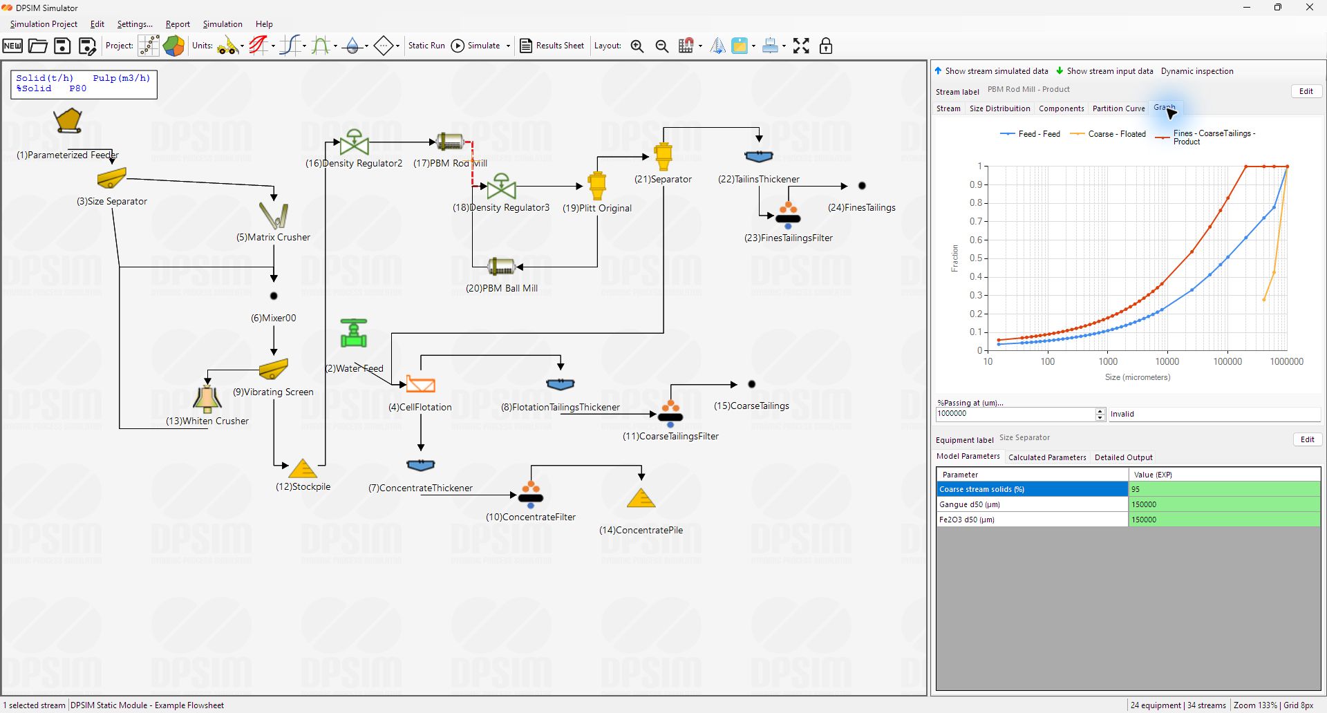
This common structure allows DPSIM to transfer material consistently from one process model to another.
It is also what allows size-by-size mass balances to be performed across an entire flowsheet.
Applying the size mesh
Once the desired size classes have been entered and checked, select:
Apply and close
DPSIM updates the project particle size mesh.
The new structure is propagated to the streams in the flowsheet, and model parameters that depend on the project size or component structure are rebuilt accordingly.
Because changing the size mesh affects the structure of particle size information throughout the project, it is good practice to define the mesh early in the simulation setup whenever possible.
Save the project after making the change.
From size classes to an actual material stream
We have now defined two fundamental characteristics of the project:
Components
What the solid material can contain.
Size classes
How the solid material can be divided by particle size.
But we still have no material entering the flowsheet.
To create a real feed, these definitions need to be combined with:
- dry solids flowrate;
- water flowrate;
- particle size distribution;
- component grades;
- component distribution across the particle size classes.
Conceptually:
Components + Size Classes + Flowrates + Composition = Feed Stream
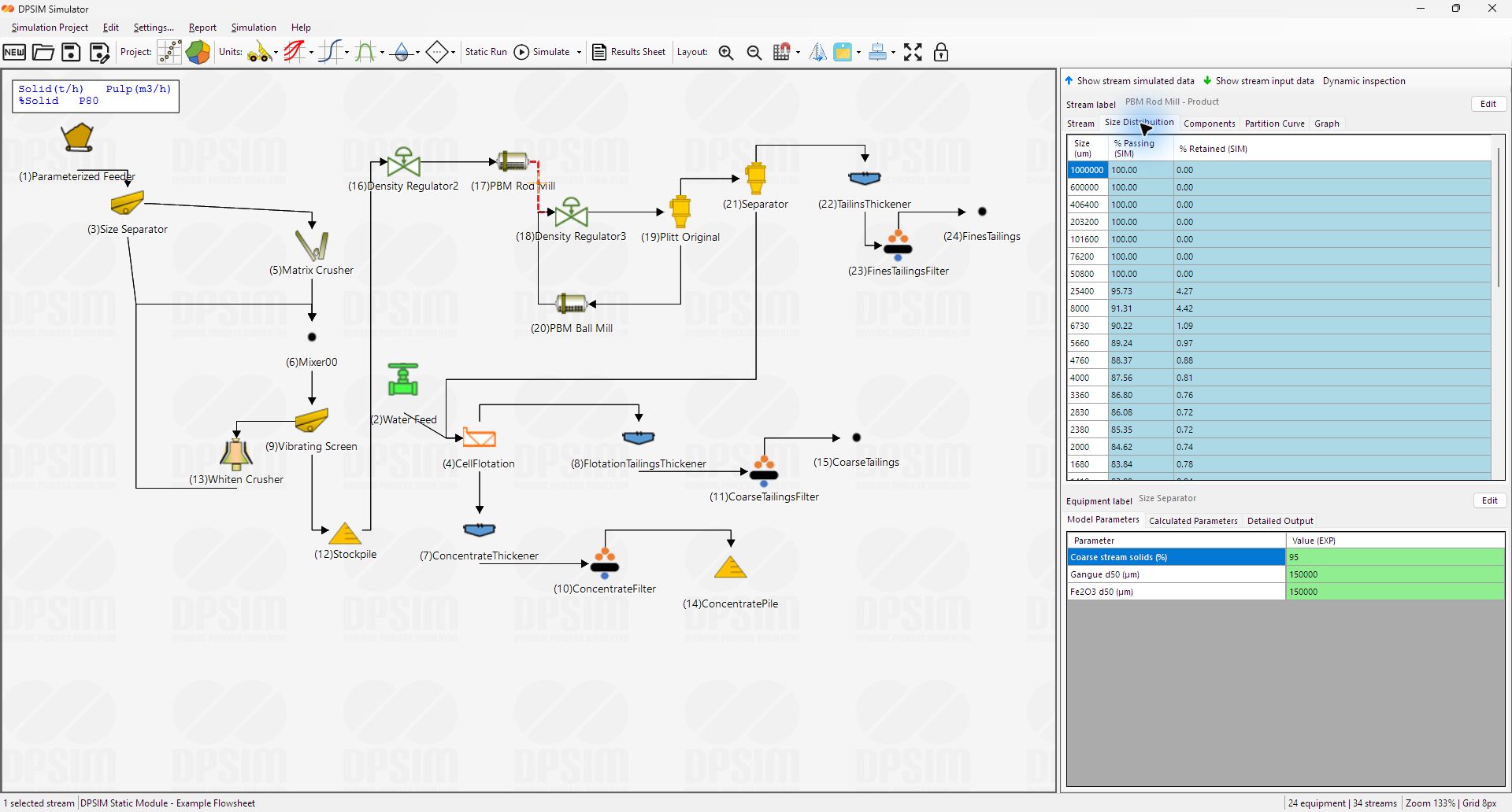
In the next tutorial, we will add the first Editable Product Stream Feed to the flowsheet and begin defining the material that will enter the simulation.