We now have a connected and organized flowsheet.
The next step is to define how each process unit will behave.
Every equipment item in DPSIM is associated with a mathematical model, and each model has its own set of parameters.
A screen may require information about aperture and dimensions.
A crusher may require operating or breakage parameters.
A hydrocyclone may require geometry and operating conditions.
A separator may require recoveries or partition parameters.
These values are configured through the equipment editor.
In this tutorial you will learn how to:
- open the equipment editor;
- identify the selected mathematical model;
- edit model parameters;
- distinguish input parameters from calculated parameters;
- understand parameter units and physical meaning;
- recognize component-dependent parameters;
- interpret calculated model outputs;
- name equipment clearly.
Opening the equipment editor
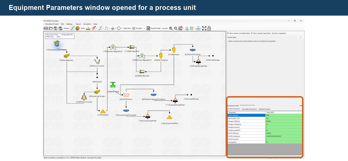
To edit a process unit, double-click the equipment icon on the flowsheet.
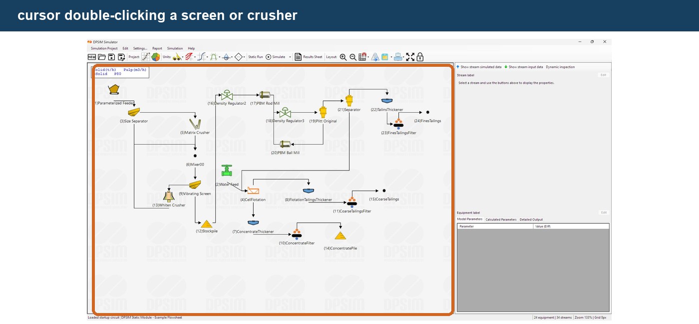
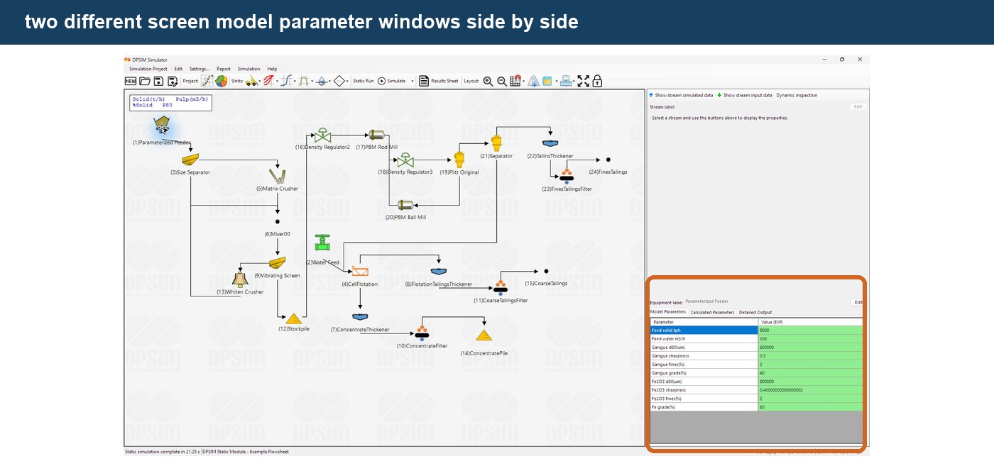
The equipment window opens with the parameters associated with the selected model.
The exact list depends on the model used by that unit.
For example, two different screen models may display completely different parameter sets even though both equipment objects represent screening operations.
This is because the parameters belong to the mathematical model, not simply to the graphical equipment type.
This reinforces an important concept from the previous tutorials:
Equipment icon ≠ mathematical model
The icon represents the process unit on the flowsheet.
The model defines how that unit is calculated.
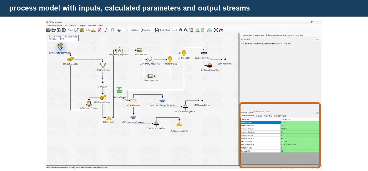
Model Parameters
The main tab is:
Model Parameters
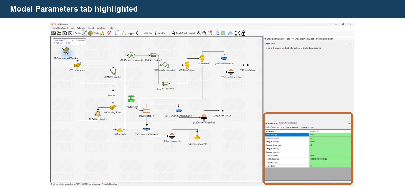
The basic table contains:
Parameter
and
Value (EXP)
The Parameter column identifies the quantity required by the model.
The Value column contains the value supplied by the user.
For example, depending on the selected model, parameters could include:
Screen opening
Number of units in parallel
Equipment width
Water split
Specific energy
P80
Recovery
d50
or other model-specific quantities.
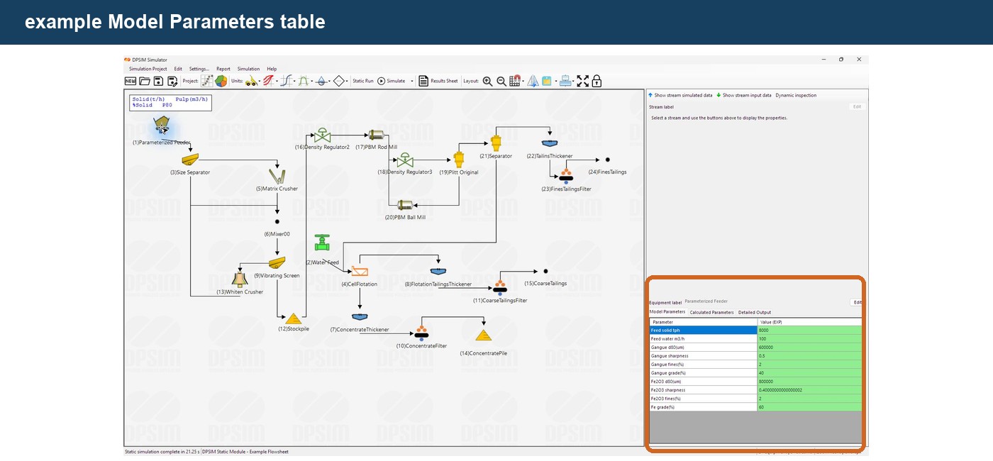
These values form part of the definition of the unit operation.
When the simulation is run, the model combines:
incoming stream data
with:
model parameters
to calculate:
output streams
and, when applicable:
calculated model parameters
Parameters depend on the selected model
There is no universal parameter list for all equipment of the same type.
Consider two hypothetical approaches for representing a screen.
One model might ask directly for:
d50
sharpness
bypass
Another might instead require:
screen opening
screen width
length-to-width ratio
deck position
and other physical or operating information.
Both models can represent classification, but they describe the process using different mathematical approaches.
The parameters shown in DPSIM therefore tell you something important about what the model expects to know.
Before entering values, understand what the selected model actually represents.
Entering parameter values
To change a parameter, edit its value in the:
Value (EXP)
column.
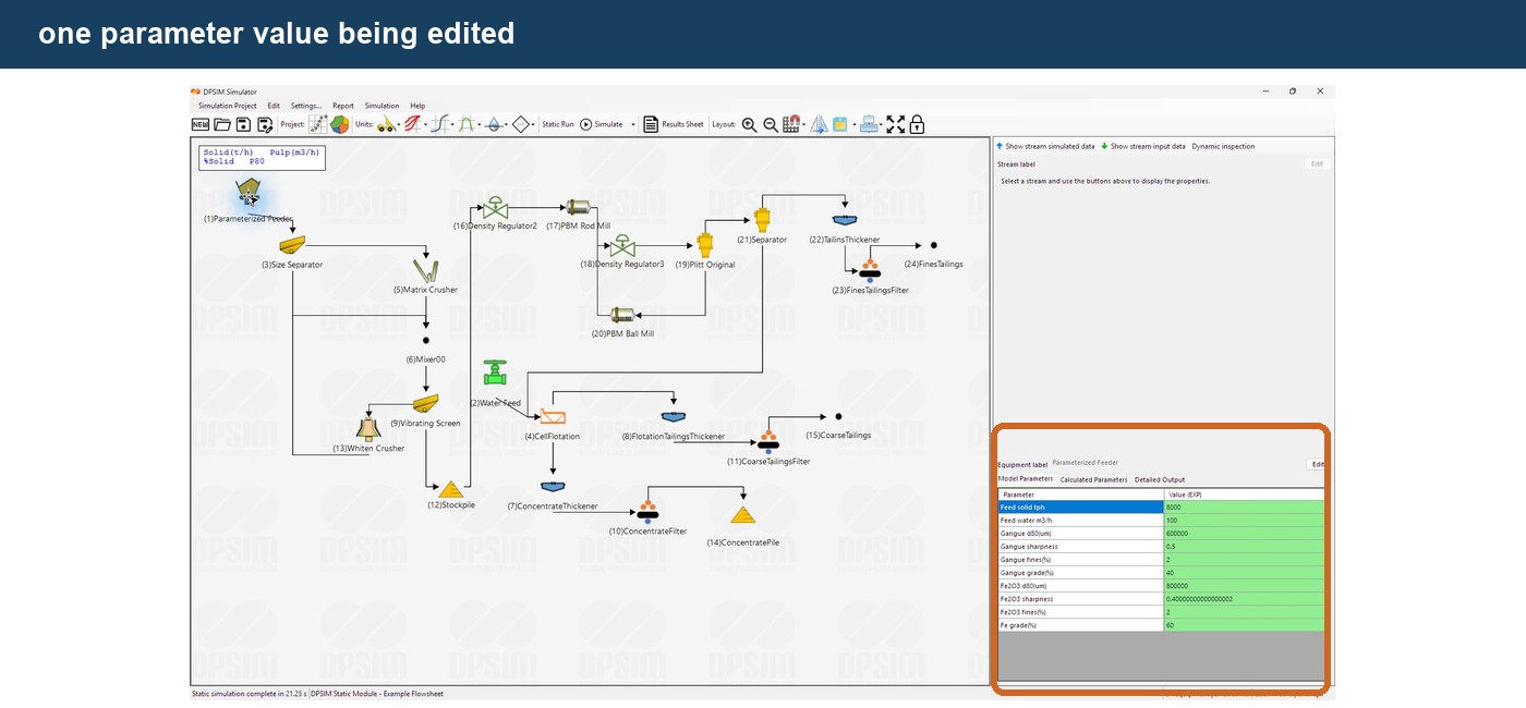
For example, a model may contain:
Screen opening = 1.0 mm
Changing this to:
0.8 mm
changes the input supplied to the mathematical model.
The next simulation will therefore use the new value.
This is one of the simplest ways to evaluate operating alternatives in DPSIM.
For example:
Case A — Screen opening = 1.0 mm
Case B — Screen opening = 0.8 mm
The resulting product streams can then be compared.
Pay attention to units
A numerical value has no engineering meaning without its unit.
Depending on the model, parameters may represent quantities such as:
- mm;
- µm;
- m;
- t/h;
- kW;
- kWh/t;
- percentages;
- dimensionless coefficients.
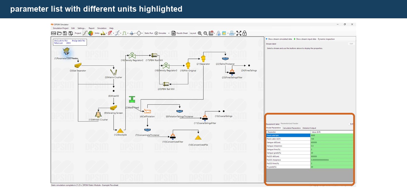
Always verify the expected unit before entering a value.
For example:
500 µm
is:
0.5 mm
Entering 500 into a field expecting millimeters instead of micrometers would change the physical meaning by a factor of one thousand.
Engineering note
Unit errors are among the easiest simulation errors to introduce and among the hardest to notice when the numerical result still appears plausible.
Whenever a model produces an unexpected result, checking parameter units should be one of the first troubleshooting steps.
Input parameters and calculated parameters
DPSIM distinguishes between quantities supplied by the user and quantities calculated by the model.
The Model Parameters tab contains the inputs.
The Calculated Parameters tab contains model-derived results.
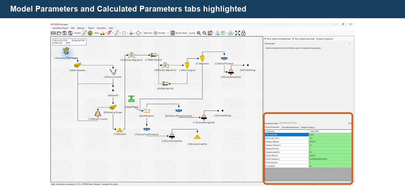
Conceptually:
Model Parameters
↓
Mathematical equations
↓
Calculated Parameters
For example, a screen model may use physical and operating parameters as inputs and calculate intermediate quantities related to its predicted classification performance.
A comminution model may calculate power or product characteristics.
A hydrocyclone model may calculate quantities derived from its geometry, operating conditions and feed.
These calculated values help explain what the model is doing internally.
Calculated Parameters
Open:
Calculated Parameters
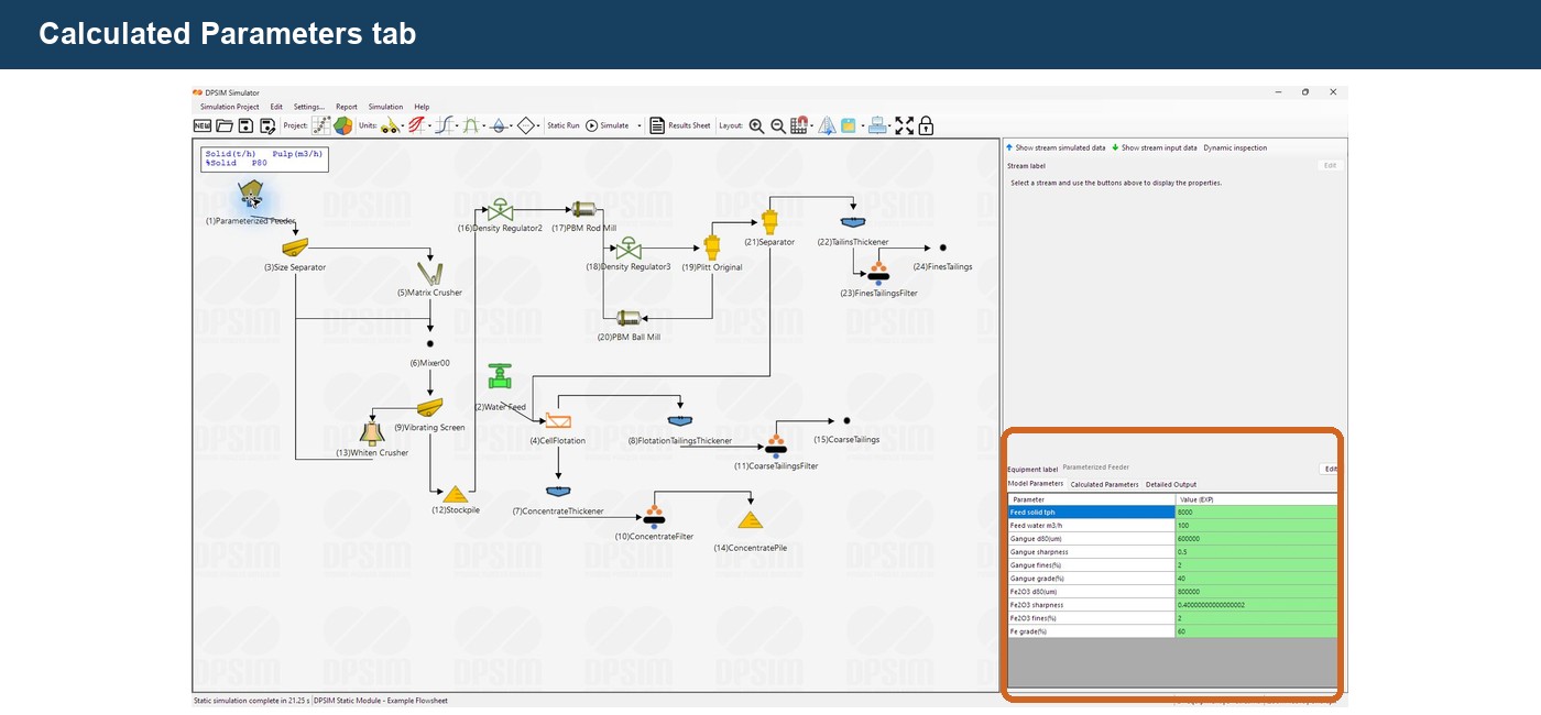
The table contains:
Parameter
and:
Value (SIM)
Unlike normal model inputs, these values are generated by the simulation and are not intended to be edited directly.
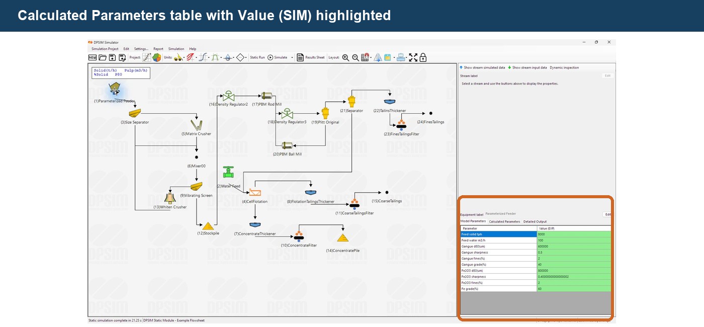
The distinction is:
Value (EXP)
User-defined model input.
Value (SIM)
Value calculated by the model.
This terminology becomes useful when comparing supplied engineering information with quantities predicted by the simulation.
Why calculated parameters are useful
The final output streams are normally the most important simulation result.
However, calculated model parameters can help explain why those streams were produced.
Consider a classification model.
The final outputs may show:
Oversize PSD
and:
Undersize PSD
But the calculated parameters might also reveal quantities such as a calculated cut size or efficiency-related parameter.
These intermediate values are particularly useful for:
- checking whether the model is behaving as expected;
- diagnosing unrealistic results;
- comparing two equipment configurations;
- understanding how changes in operating conditions affect model behavior.
They should therefore be treated as engineering information, not merely software diagnostics.
Example: a screen model
Suppose a screen model requires parameters such as:
Number in parallel
Screen width
Length/width ratio
Screen opening
Deck position
and:
Water to coarse product
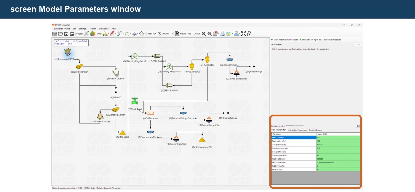
These parameters describe both the equipment configuration and its operating behavior.
When the simulation is run, the model uses them together with the incoming stream PSD.
Conceptually:
Feed PSD
Screen geometry
Operating parameters
↓
Screen model
↓
Oversize PSD + Undersize PSD
Some models may also generate calculated parameters describing their internal prediction.
This is fundamentally different from simply specifying a fixed separation efficiency.
Some parameters depend on components
Not every parameter is necessarily global for the complete stream.
Certain models define parameters separately for each solid component.
For example, a component-based separator may contain parameters such as:
Hematite recovery
Quartz recovery
or classification parameters defined independently for each component.
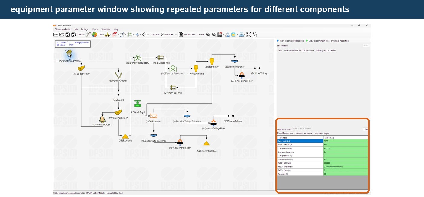
This is possible because the project components were defined at the beginning of the simulation.
If the project contains:
Hematite
and:
Quartz
a model can assign different behavior to each one.
This is one of the mechanisms by which DPSIM can predict changes in product grade.
Some models also depend on particle size
Mineral processing performance is frequently size-dependent.
A separation process may recover coarse particles differently from fine particles.
A comminution model may calculate breakage separately across the project size mesh.
A classification model fundamentally determines how different sizes partition between products.
For these models, the size classes defined earlier become part of the calculation structure.
This is why changing the project size mesh may also require model-dependent parameter structures to be rebuilt.
The equipment model, material components and size mesh are not isolated definitions.
They work together.
Model parameters should come from engineering information
Default values are useful for initializing a model, but they should not automatically be assumed to represent the process being studied.
Whenever possible, model parameters should come from appropriate sources such as:
- equipment specifications;
- plant operating data;
- laboratory tests;
- pilot tests;
- sampling campaigns;
- vendor information;
- published model correlations;
- model calibration.
The reliability of a simulation depends heavily on the quality of these inputs.
A mathematically sophisticated model does not compensate for poor parameter data.
Default values are not calibration
When equipment is added to the flowsheet, its model may already contain default parameter values.
This allows the model structure to be created immediately.
However:
default value ≠ validated plant value
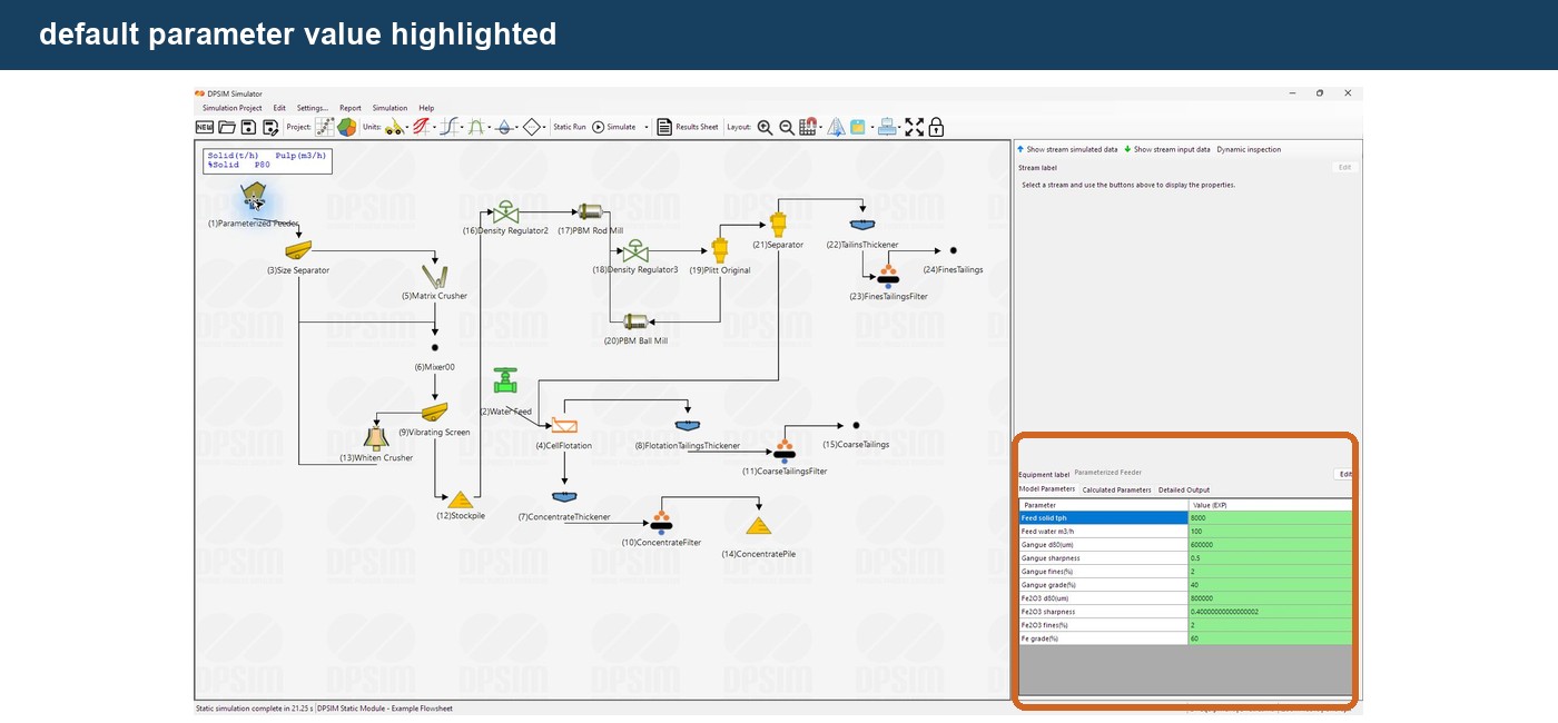
Before using simulation results for engineering conclusions, verify which parameters are:
measured
specified
estimated
assumed
or:
calibrated
This distinction should also be documented when the simulation is used in an engineering study.
Change one thing at a time when learning a model
When first exploring a new model, a useful approach is to modify one important parameter at a time.
For example:
Base case
Screen opening = 1.0 mm
then:
Alternative
Screen opening = 0.8 mm
Run the simulation again and observe the change in the products.
This helps build an intuitive understanding of the model.
Changing many parameters simultaneously can make it difficult to determine which one caused the observed result.
This approach is particularly useful when learning more complex models.
Equipment labels
The equipment editor also allows the flowsheet label to be changed.
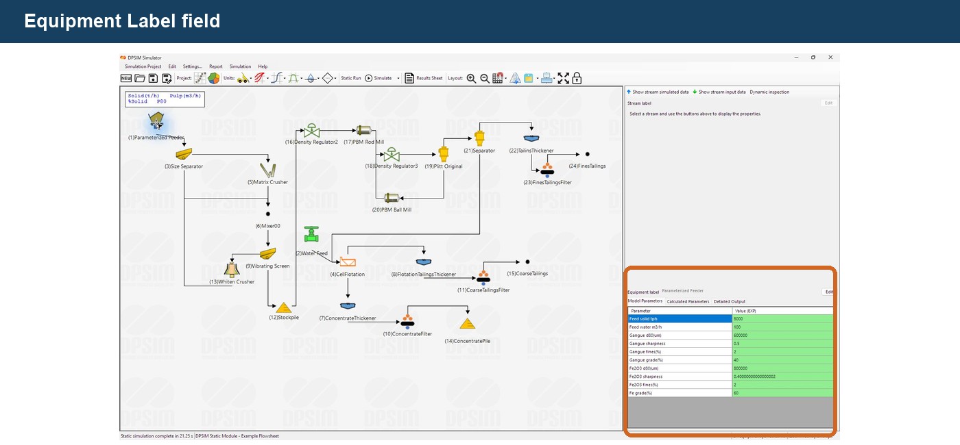
Instead of leaving generic labels, use names that describe the process unit clearly.
For example:
Primary Crusher
Secondary Screen
Ball Mill
Cyclone Cluster
Rougher Flotation
or the plant equipment tag:
CR-001
SC-002
BM-001
Clear labels become increasingly important when the simulation contains many similar units.
They also make result tables and exported information easier to interpret.
Detailed Output
Some models can provide additional information through the:
Detailed Output
tab.
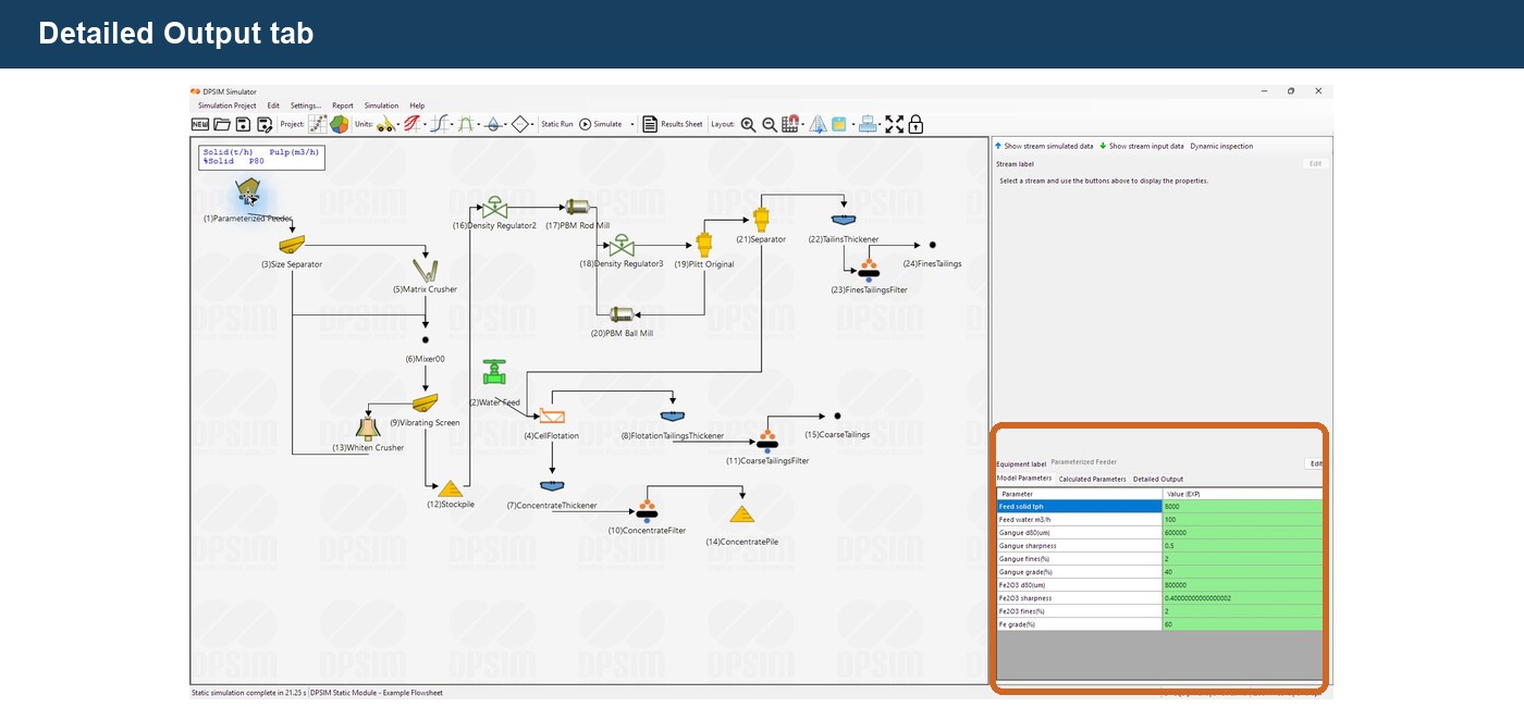
This area can display model-specific calculation information when the model provides it.
The information available depends on the selected model.
For basic use, the primary workflow remains:
Model Parameters → Run Simulation → Calculated Parameters and Stream Results
Detailed output becomes more useful when examining the internal behavior of a particular model.
Do not compare parameters from different models blindly
Two models representing the same process may use parameters with completely different physical meanings.
For example, one crusher model may use empirical breakage parameters while another may directly define aspects of the product distribution.
A value of:
0.8
in one model has no necessary relationship to a value of:
0.8
in another.
Parameters should always be interpreted in the context of the equations and assumptions of the selected model.
Later in this series, individual model tutorials will explain those equations and parameter definitions in more detail.
The model reference is part of the workflow
When configuring a model that is not already familiar, consult its documentation.
A useful model reference should answer:
- What does the model calculate?
- What does each parameter represent?
- Which units are used?
- What equations are implemented?
- What assumptions are made?
- Which parameters require calibration?
- What are the model limitations?
- Where does the model come from?
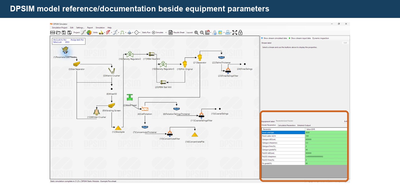
Model documentation is especially important when two models are available for the same process operation.
Selecting a model should be an engineering decision, not simply a software selection.
Preparing the flowsheet for simulation
Using the example built through this tutorial series:
Editable Feed → Crusher → Screen
open each process equipment item and review its Model Parameters.
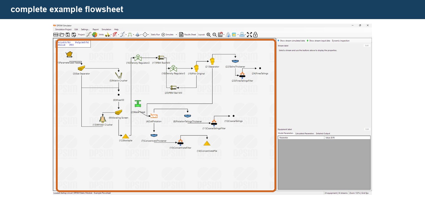
For now, the objective is not to perform a detailed crusher or screen model study.
Simply confirm that:
- the correct model was selected;
- the parameter values are physically reasonable;
- the units are understood;
- the equipment labels are clear;
- all required process connections exist.
The flowsheet is now ready for its first static calculation.
From model definition to simulation
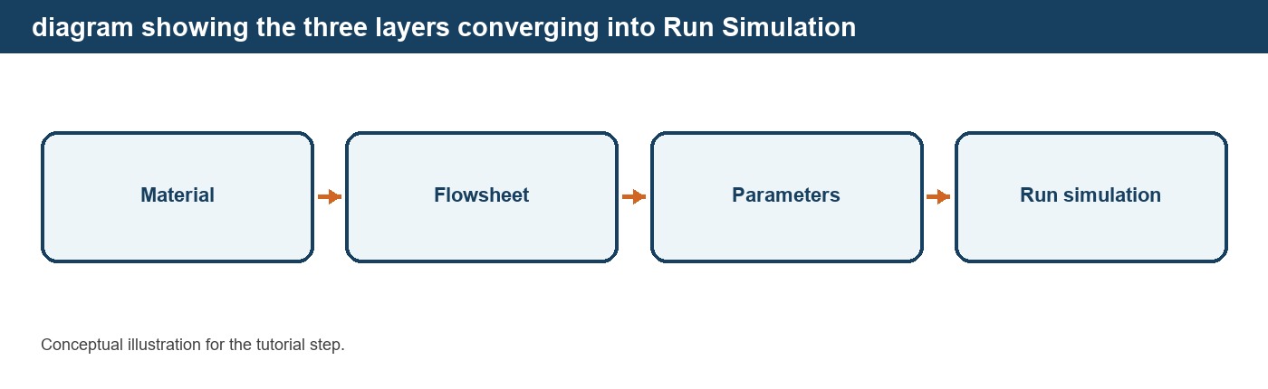
We have now defined the three fundamental layers of the DPSIM model:
Material
Components, size distribution, composition and flowrates.
Flowsheet
Equipment and stream connectivity.
Models
Parameters describing the behavior of each process unit.
Together:
Material + Flowsheet + Models → Simulation
The next tutorial will show how to run the first static simulation, how DPSIM propagates material through the flowsheet, and what to check when the calculation does not produce the expected result.