As a DPSIM flowsheet grows, direct connections between equipment can quickly become difficult to read.
Recycle streams may need to return to upstream equipment. Parallel process routes can cross each other. Streams may need to pass around equipment instead of directly through the middle of the flowsheet.
DPSIM allows routing nodes to be added to material streams so their graphical path can be adjusted without changing the process itself.
In this tutorial, we will use stream nodes to organize the flowsheet and make process connections easier to follow.
In this tutorial you will learn how to:
- understand what a stream node represents;
- add a node to an existing stream;
- move stream nodes;
- use multiple nodes to route a stream;
- remove unnecessary nodes;
- use nodes to organize recycle streams;
- distinguish graphical routing from process topology.
What is a stream node?
A stream node is an intermediate graphical point inserted between the source and destination of a material stream.
Consider a direct connection:
Crusher → Screen
The stream normally follows a direct path between the two equipment ports.
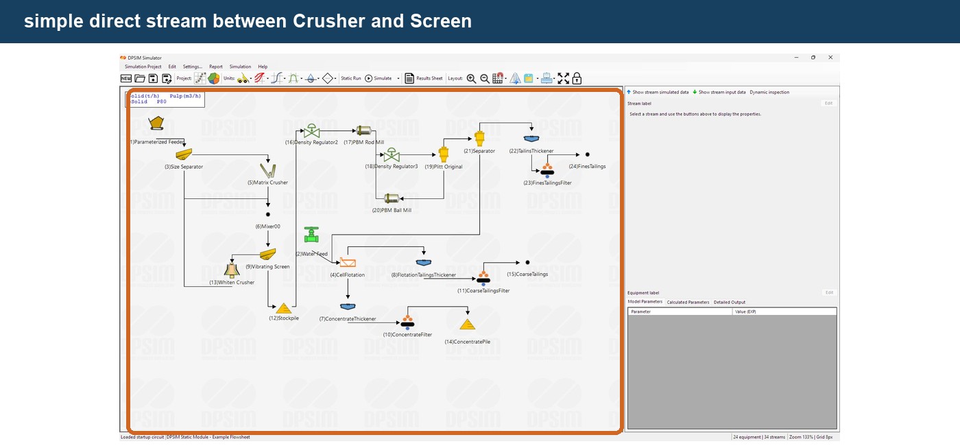
A routing node allows the stream path to pass through an intermediate point:
Crusher → Node → Screen
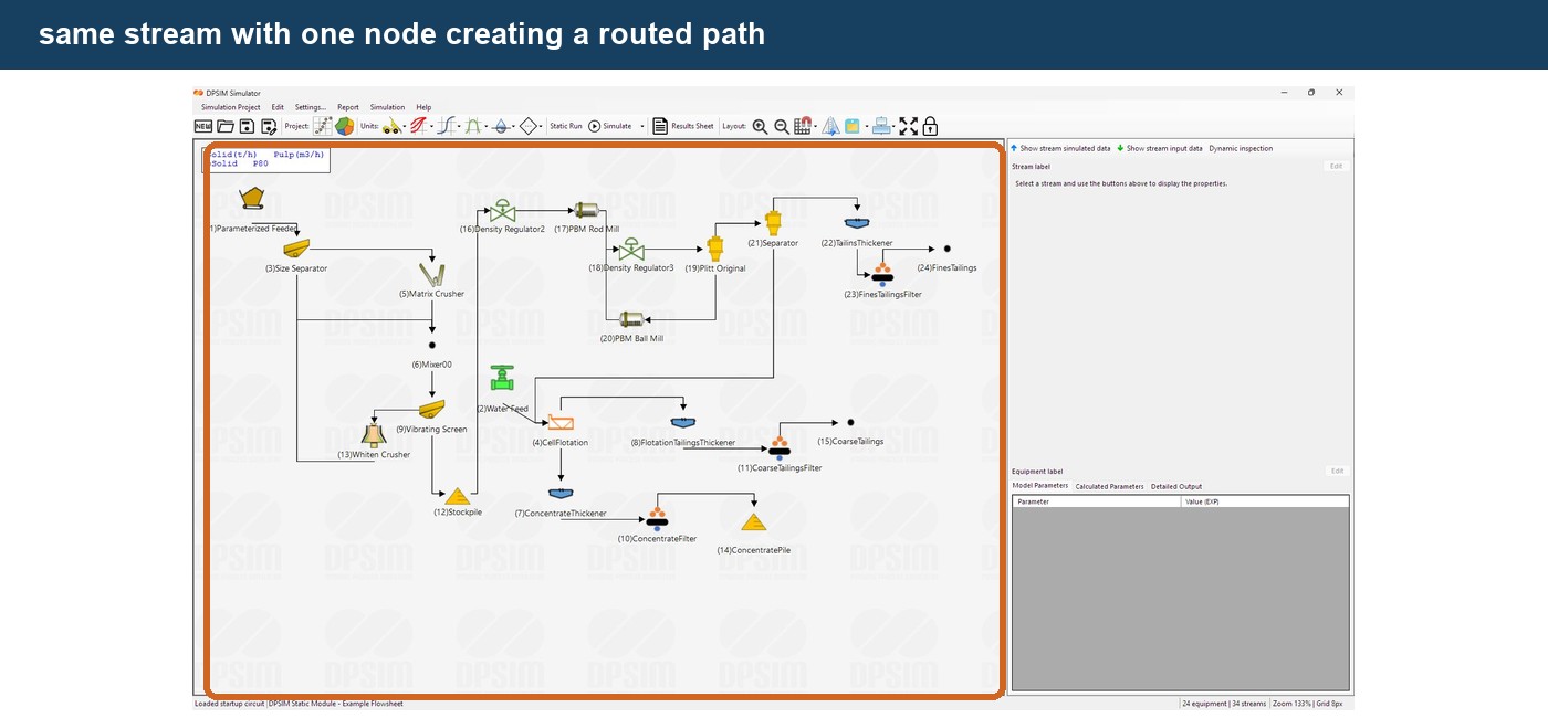
The important point is that this does not create another process operation.
The stream is still exactly the same stream.
Its:
- source equipment;
- destination equipment;
- material flow;
- PSD;
- composition;
- calculated properties
remain unchanged.
Only its graphical path on the flowsheet changes.
Why use stream nodes?
For a small flowsheet, direct connections are usually sufficient.
For example:
Feed → Crusher → Screen → Product
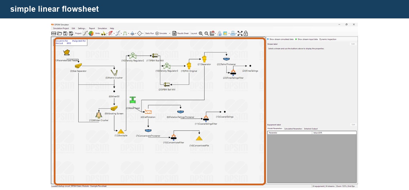
But consider a closed crushing circuit:
Crusher → Screen
with:
Screen Oversize → Crusher
The recycle stream needs to return upstream.
A direct line may cross equipment or other streams.
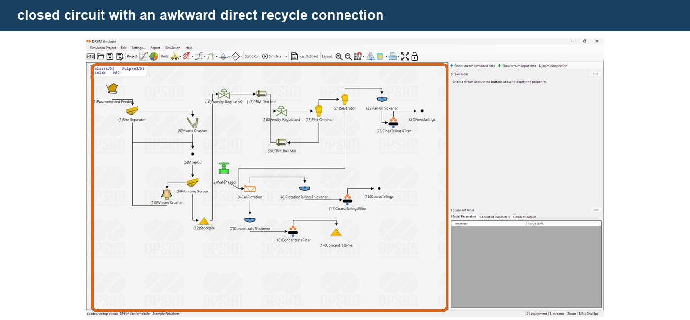
Using routing nodes, the recycle can instead be drawn around the main process:
Screen Oversize
↓
← ← ← recycle route
↓
Crusher
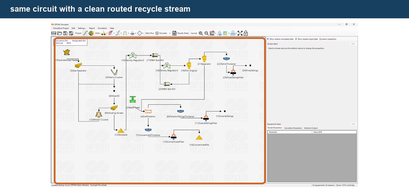
The mathematical flowsheet is identical.
The second version is simply easier to understand.
Adding a node to a stream
Move the cursor to the point on the stream where you want to create the routing node.
Right-click directly on the stream.
Open:
Stream → Add Node
DPSIM inserts a new routing point at the location where the stream was clicked.
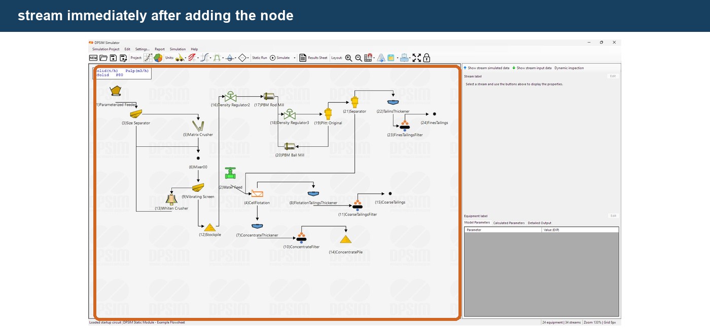
The stream now passes through that intermediate point.
If Snap To Grid is enabled, the node position follows the flowsheet grid.
This can help create cleaner and more consistent routing.
Moving a stream node
Select the stream.
Its routing points become available for editing.
Drag the node to the desired position.
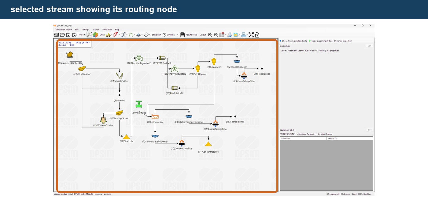
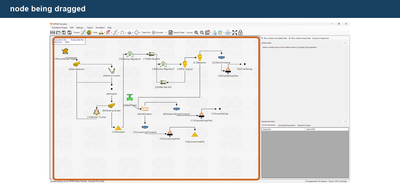
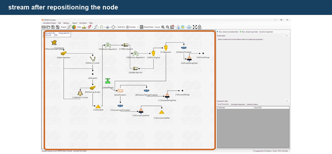
Moving the node changes only the graphical geometry of the stream.
The connection still represents exactly the same relationship:
same source → same destination
This means flowsheet organization can be improved at any time without affecting the simulation calculation.
Using more than one node
A single node creates one intermediate change in the stream path.
More complex routing may require multiple nodes.
For example, suppose a recycle stream needs to pass below several equipment units before returning upstream.
Add additional nodes using:
Right-click stream → Stream → Add Node
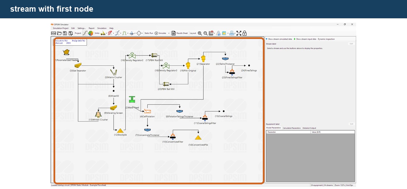
Add another:
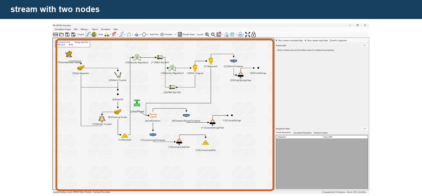
And reposition them:
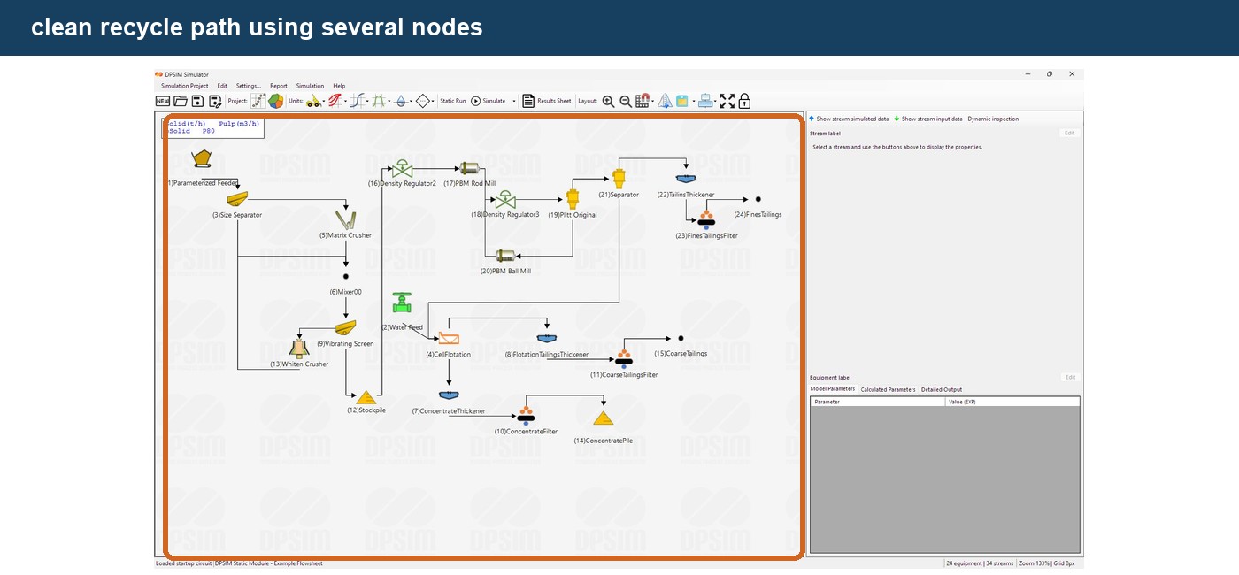
Multiple nodes allow you to create a route such as:
down → across → up
instead of a diagonal line crossing the process area.
This is particularly useful for:
- recycle streams;
- bypasses;
- parallel circuits;
- multiple product streams;
- large flowsheets.
Using the grid for cleaner routing
If you want the flowsheet to have a more regular appearance, enable:
Snap To Grid
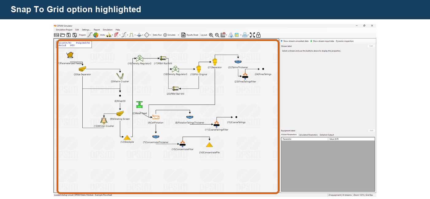
When a node is added with snapping enabled, DPSIM aligns its position to the project grid.
This makes it easier to construct streams with consistent spacing.
For example:
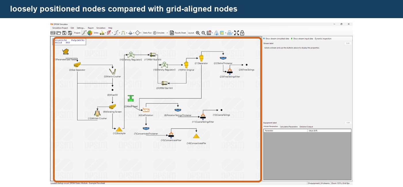
There is no requirement that every stream follow a perfectly orthogonal route.
The objective is simply to make the process easy to read.
Removing a stream node
If a routing point is no longer necessary, right-click on the stream near the node and select:
Stream → Remove Node
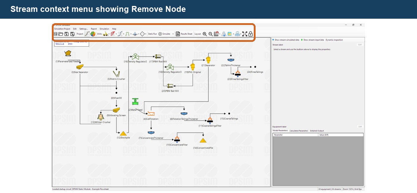
DPSIM removes the corresponding intermediate point and redraws the stream using the remaining routing points.
Removing a node does not remove the material stream itself.
It only removes one of its graphical routing points.
This is different from deleting the complete stream connection.
Adding nodes from the toolbar
The DPSIM Static Module also provides dedicated toolbar commands for stream nodes.
Select a single stream.
The commands:
Add stream node
and:
Remove stream node
become available.
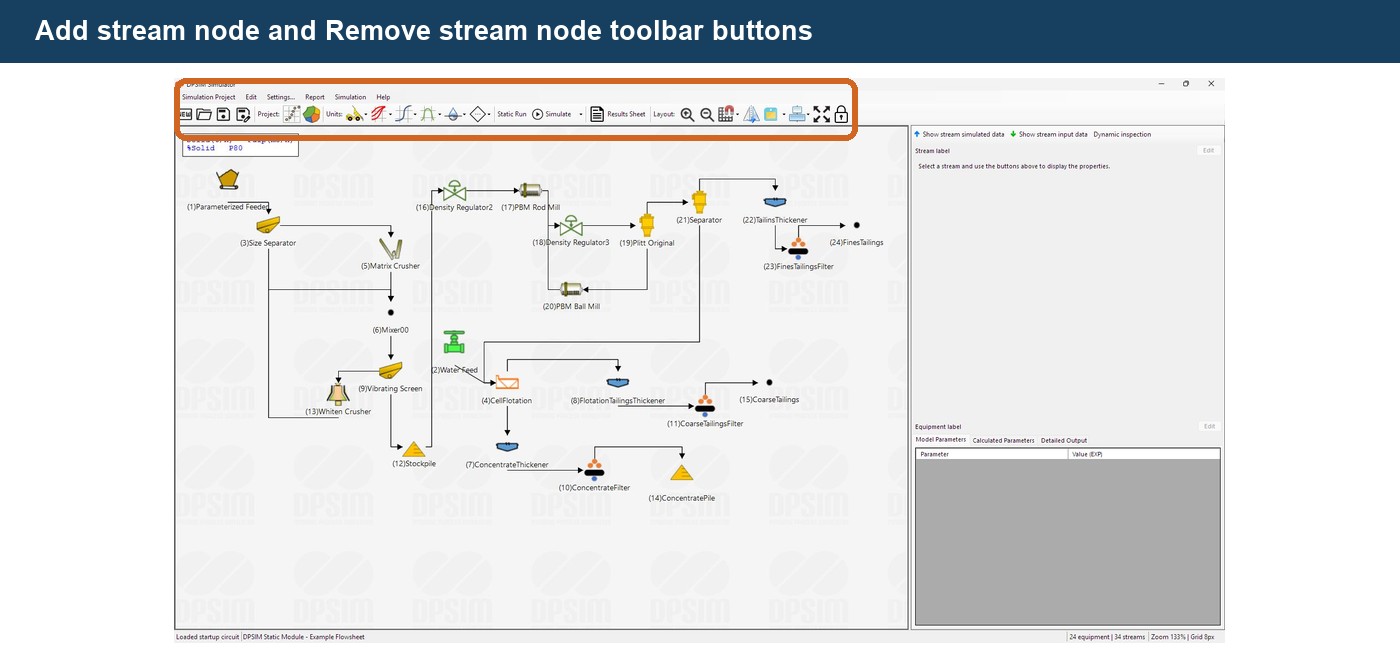
When Add stream node is used from the toolbar, DPSIM automatically inserts a node around the middle of the longest segment of the selected stream.
You can then drag the new node to the desired position.
The toolbar method is convenient when you simply want another routing point.
The right-click method is more precise when you already know where you want the node to appear.
DPSIM also provides the corresponding remove command for a selected stream.
Nodes do not split a stream
This distinction is important.
Adding a node does not create two material streams.
For example:
Crusher → Node → Screen
is still one stream.
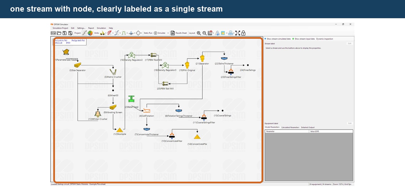
The node does not perform:
- a mass balance;
- a split;
- mixing;
- storage;
- separation;
- any process calculation.
If the material needs to be physically divided between two destinations, use a Splitter.
If different streams need to be combined, use a Mixer.
A routing node has only one purpose:
flowsheet layout.
Routing a recycle stream
Recycle circuits are one of the most useful applications for stream nodes.
Consider:
Crusher → Screen
The screen undersize leaves as the final product, while the oversize returns to the crusher.
Conceptually:
Crusher → Screen → Undersize Product
and:
Screen Oversize → Crusher
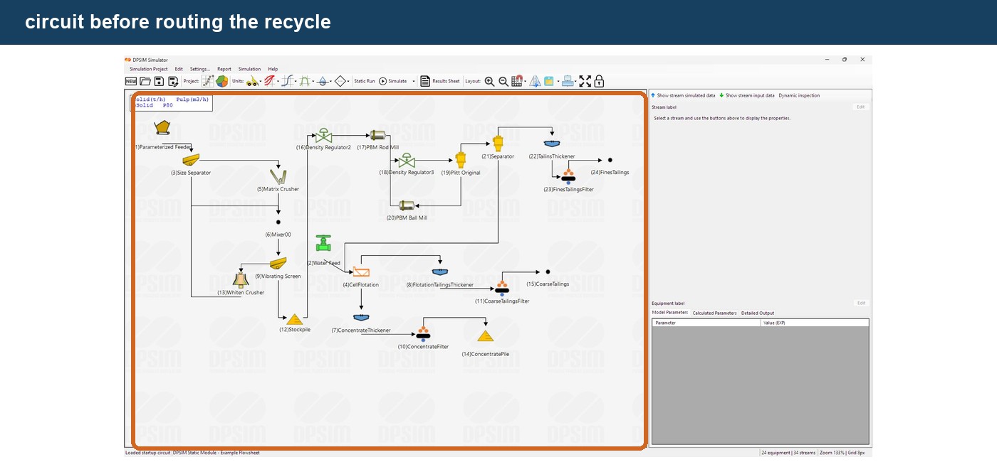
A direct recycle line can make the circuit difficult to read.
Add nodes to the oversize stream and route it around the main process.
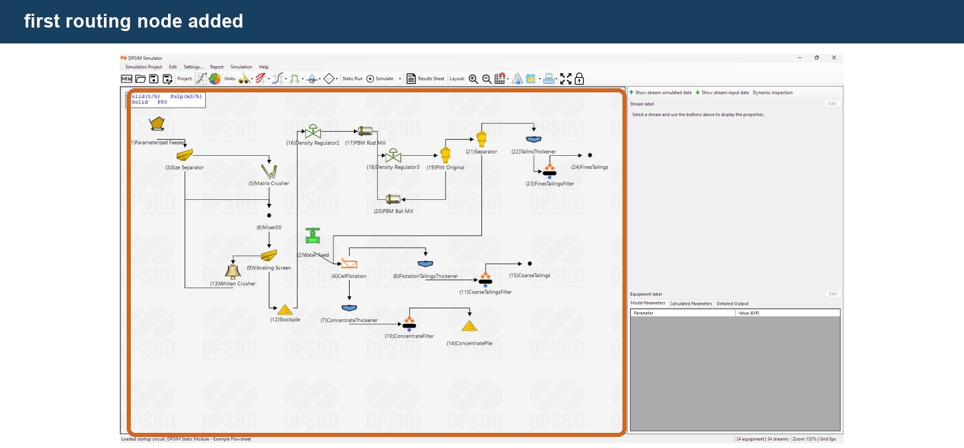
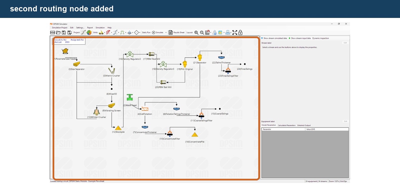
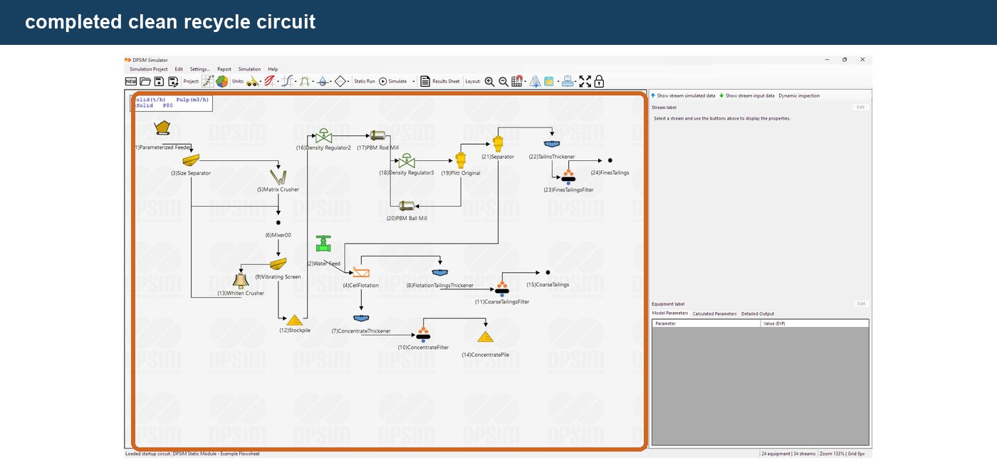
The recycle relationship becomes immediately visible.
This will be important later when we simulate closed crushing and grinding circuits, where circulating loads are part of the process calculation.
Avoid unnecessary nodes
Nodes are useful, but adding too many can make a flowsheet harder rather than easier to read.
Compare:
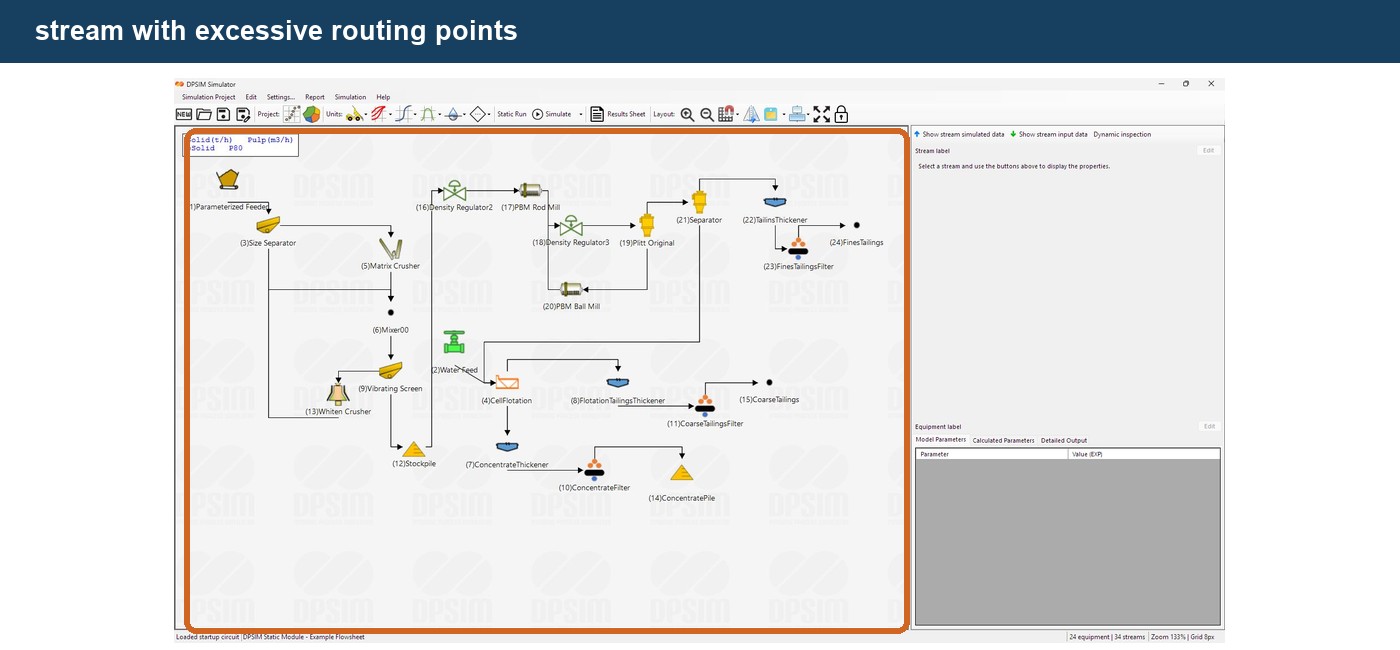
with:
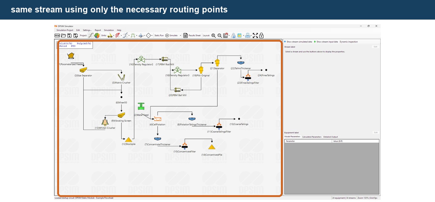
Use enough nodes to make the route clear, but avoid unnecessary changes in direction.
A good flowsheet should allow someone to understand the major material paths quickly.
Engineering note
Flowsheet graphics are part of engineering communication.
A simulation may be mathematically correct and still be difficult to review if its graphical representation is unclear.
When another engineer opens a DPSIM project, the main process path, products and recycle streams should be apparent before individual model parameters are inspected.
Keep the main process path simple
A useful layout convention is to keep the primary material path relatively straight:
Feed → Primary Process → Secondary Process → Product
and route secondary streams around it.
For example:
main process: left to right
recycles: below or above the main process
secondary products: downward
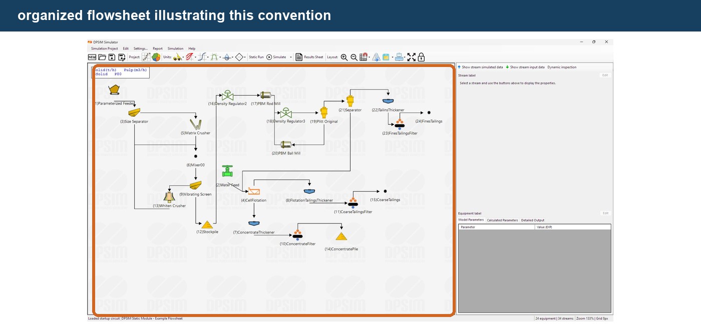
This is not a calculation requirement.
It is simply a useful way to keep increasingly complex flowsheets understandable.
Nodes and process topology are independent
Consider these two diagrams:
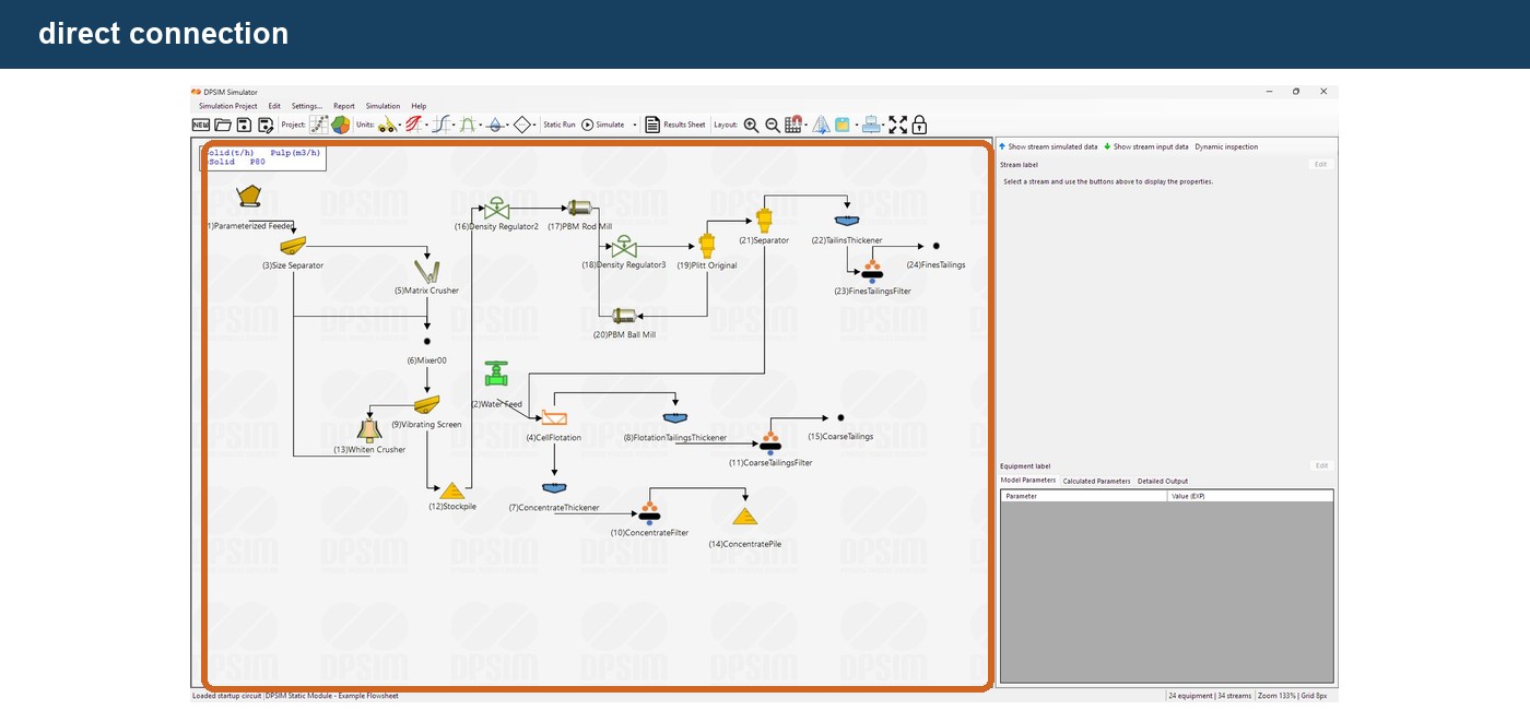
Flowsheet A
A direct stream connects a crusher to a screen.
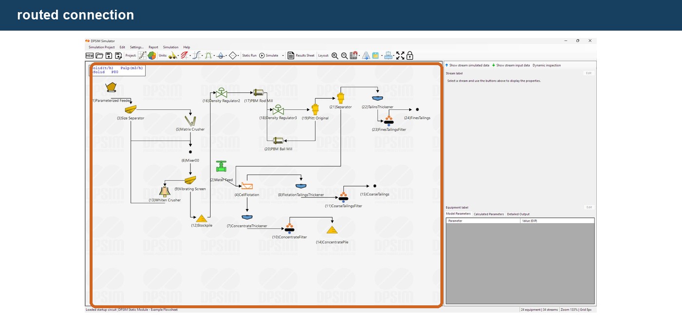
Flowsheet B
The same stream passes through three routing nodes before reaching the screen.
From the simulation perspective:
Flowsheet A = Flowsheet B
The source and destination have not changed.
The material calculation has not changed.
Only the graphical representation has changed.
This distinction between process topology and drawing geometry is useful when editing large simulation projects.
Building a clean flowsheet
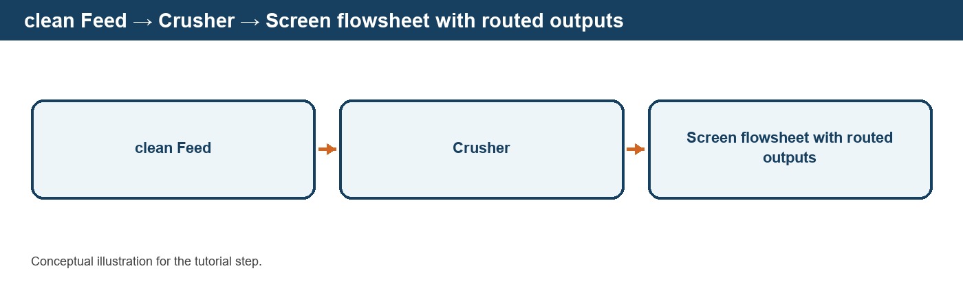
Using the example developed throughout this tutorial series, we can now organize:
Editable Feed → Crusher → Screen
with the screen outputs arranged clearly.
For example:
Undersize → Product
and, if desired later:
Oversize → recycle or additional crushing
At this point we have learned how to:
- define the material;
- add process equipment;
- connect equipment;
- organize stream routing.
The basic flowsheet structure is now ready.
The next step is to configure how each process unit actually behaves.
From flowsheet topology to model parameters
Every process equipment instance in DPSIM is associated with a mathematical model.
That model contains parameters that determine its behavior.
For a screen, these may describe quantities related to:
- aperture;
- dimensions;
- efficiency;
- partition behavior;
- water split.
For a crusher, they may include operating and breakage parameters.
For a separator, they may include recoveries or partition characteristics.
The exact parameters depend on the selected model.
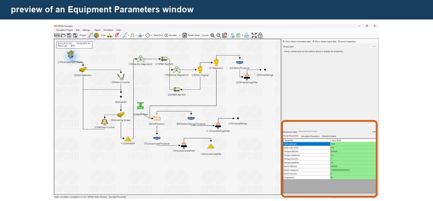
In the next tutorial, we will open the Equipment Parameters interface and see how DPSIM organizes:
model inputs
calculated parameters
units
and
component-dependent parameters.