We now have two essential elements on the DPSIM flowsheet:
a defined material feed
and
a process equipment model
But simply placing them next to each other does not create a process.
The units must be connected by a material stream.
Streams define the path followed by solids, water, particle size distributions and components through the simulation.
In this tutorial, we will create the first process connection and explore how streams define the flowsheet structure.
In this tutorial you will learn how to:
- understand input and output ports;
- create a material stream between two units;
- understand stream direction;
- connect equipment with multiple products;
- recognize invalid connections;
- understand what information travels through a DPSIM stream.
Streams define the process topology
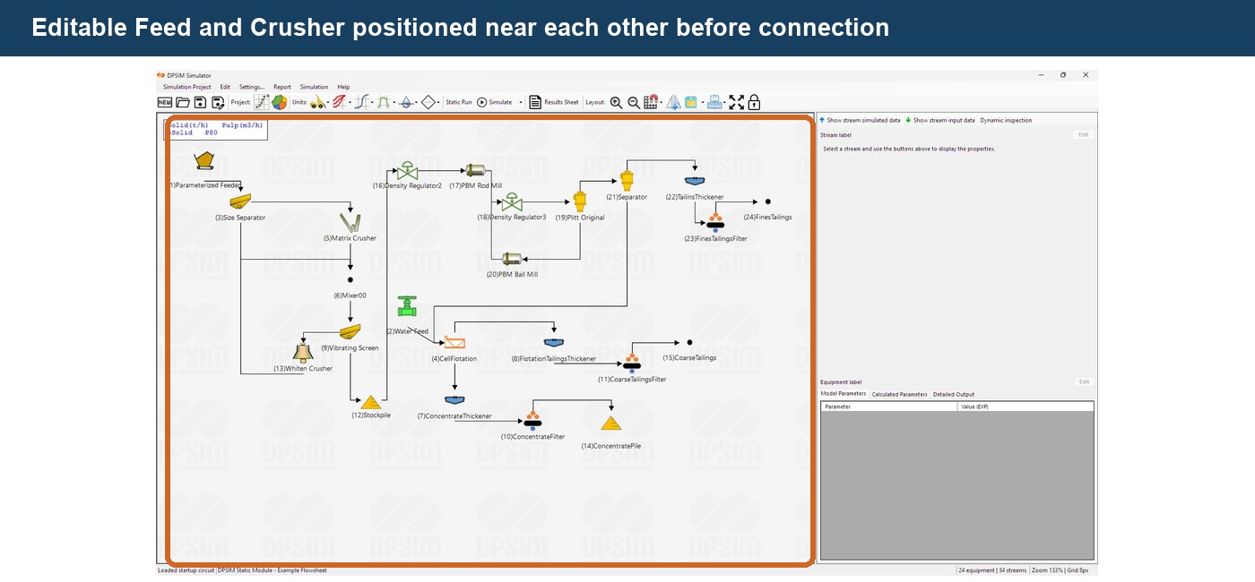
In the previous tutorial, we positioned an Editable Feed and a process unit beside each other.
For example:
Editable Feed Crusher
Their graphical position suggests a process sequence, but DPSIM does not use position to determine how material flows.
Only an explicit stream connection creates the relationship:
Editable Feed → Crusher
This distinction is important.
Two equipment objects may be positioned beside each other without being connected.
Likewise, units located far apart on the canvas can still be part of the same process if a stream connects them.
Therefore:
equipment position defines the drawing
while:
stream connections define the process
Input and output ports
Each process unit has one or more connection points called ports.
Ports have a defined direction.
An input port receives material from an upstream stream.
An output port generates a stream that can be sent to another unit.
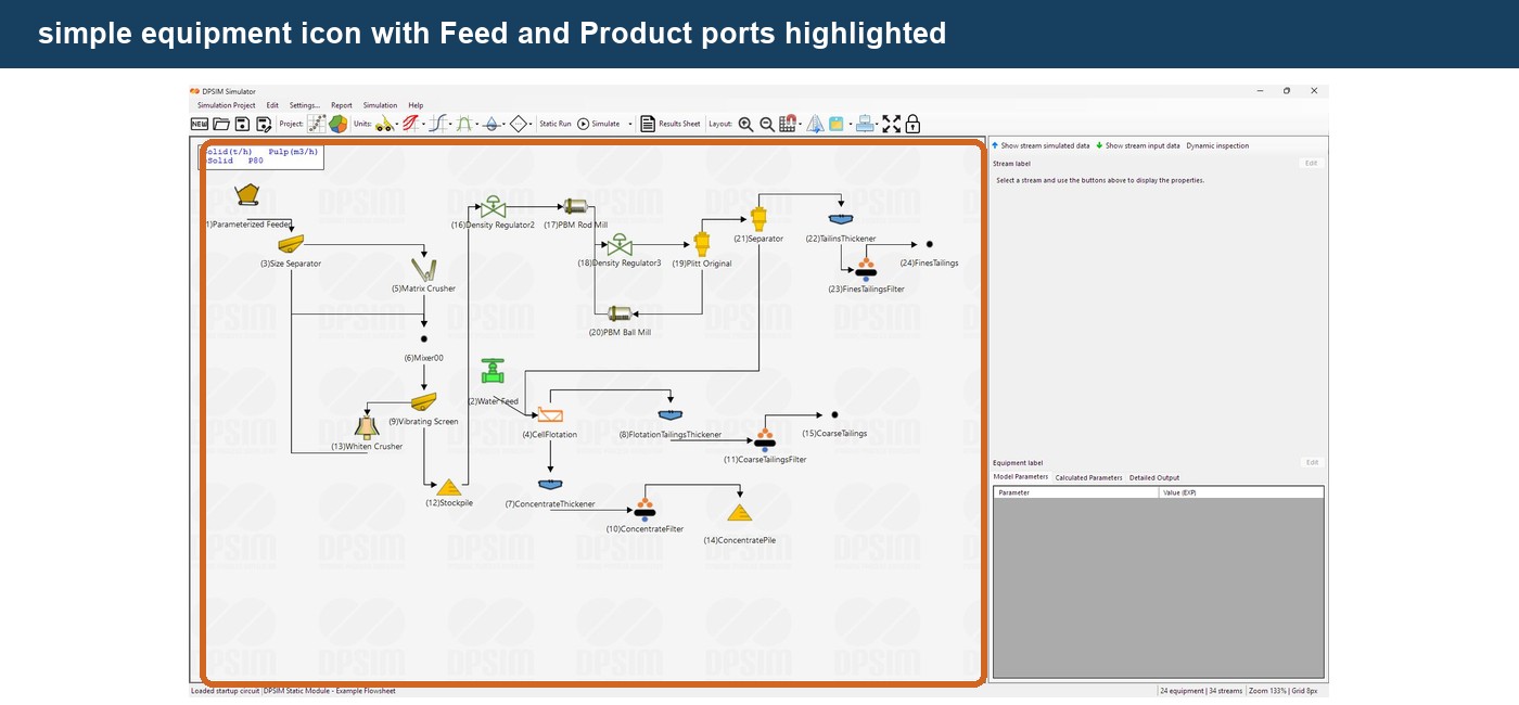
For a simple process unit:
Feed → Equipment → Product
the equipment normally contains:
Feed — input port
and
Product — output port
Other equipment can contain more than one output.
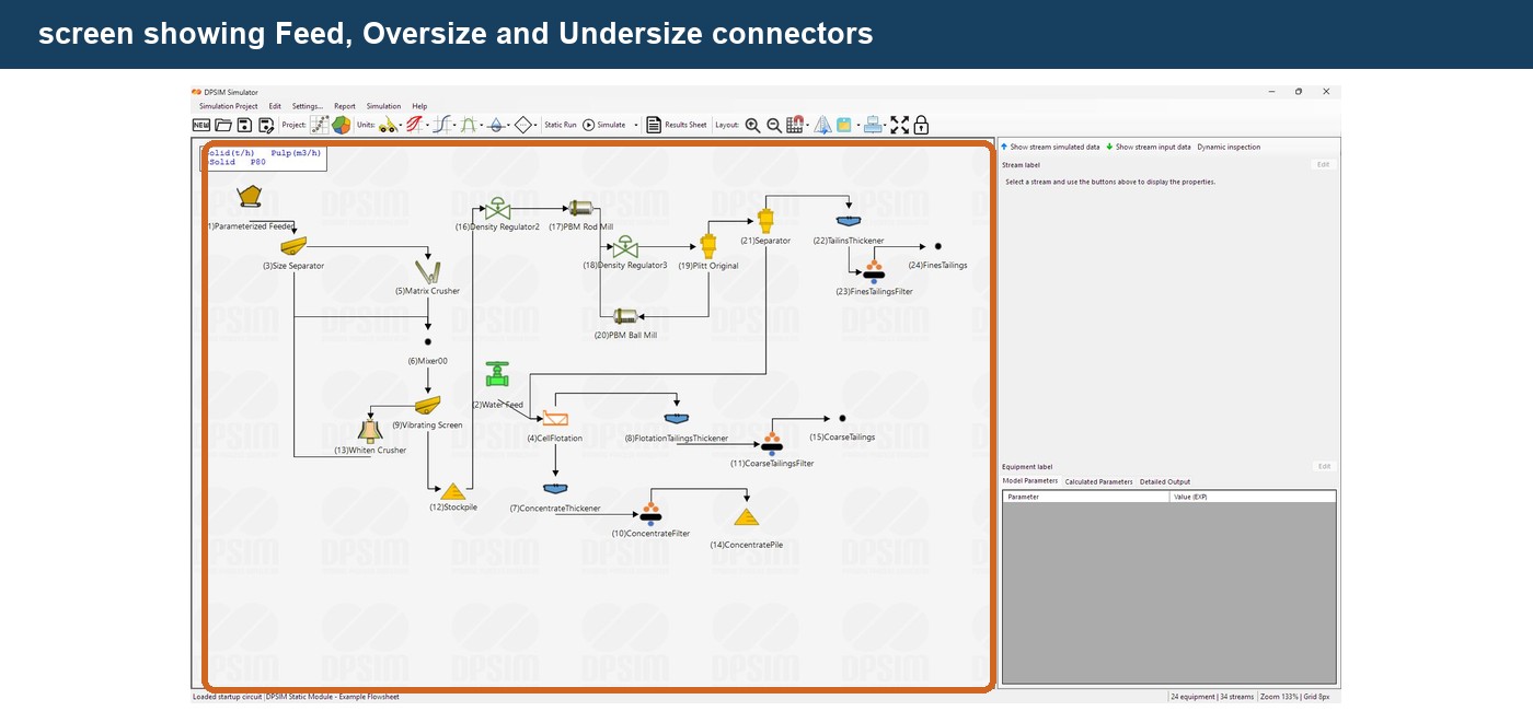
A screen, for example, may have:
Feed
Oversize
Undersize
A separator may instead use outputs such as:
Concentrate
and
Tail
The port names therefore carry process meaning. They identify what each connection represents physically.
Creating a stream
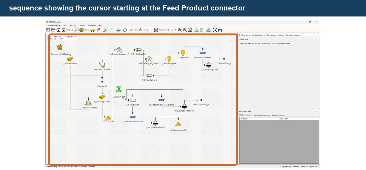
To connect two units, locate the output connector of the upstream equipment.
For our example, use the Product output of the Editable Feed.
Click and hold the connector, then drag the connection toward the Feed input connector of the downstream equipment.
Release the mouse over the input connector.
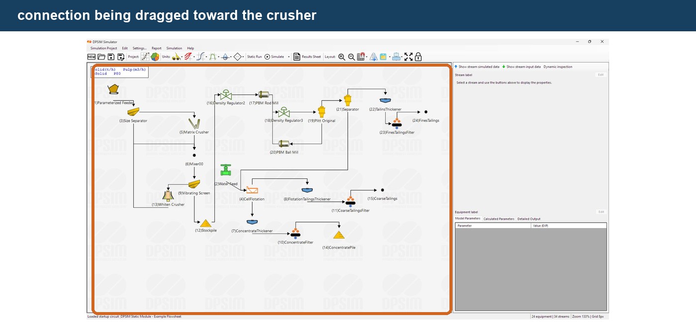
DPSIM creates the material stream between the two units.
The flowsheet now represents:
Editable Feed → Crusher
The stream is associated with the output port of the upstream unit and its destination becomes the selected input port of the downstream unit.
Stream direction matters
A DPSIM stream always has a process direction:
Source → Destination
For a valid connection, start from an output port and connect to an input port.
For example:
Product → Feed
is valid.
Trying to create the connection in the opposite direction:
Feed → Product
is not valid.
DPSIM validates this automatically.
A feed/input port cannot be used as the origin of a process stream, and an output port cannot be used as its destination.
This prevents connections that would contradict the process direction.
The arrow represents material flow
The stream line includes a direction indicating the material flow through the flowsheet.
For example:
Feed → Crusher → Product
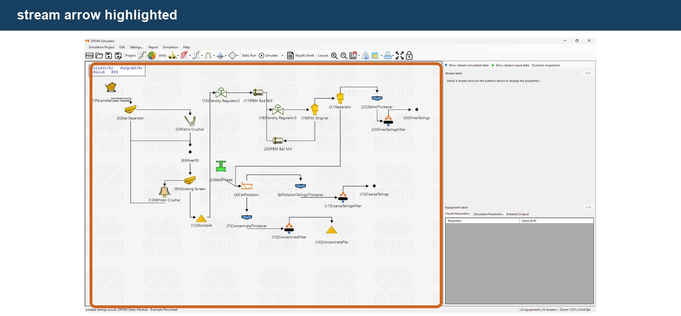
When building larger flowsheets, this makes it possible to visually follow the material from the plant feed through each unit operation to the final products.
A well-organized flowsheet should make this direction easy to understand without requiring the user to inspect every individual connection.
What does a stream carry?
A DPSIM stream is much more than a line between two icons.
It carries the complete material description calculated by the simulator.
Depending on the project and simulation state, a stream can contain information such as:
- solids flowrate;
- water flowrate;
- total mass flowrate;
- percent solids;
- solids density;
- pulp density;
- volumetric flowrate;
- particle size distribution;
- P80;
- component grades;
- component mass flowrates;
- component distribution by particle size.
This is why the definitions created in the previous tutorials are important.
The stream transports the same structured material representation through every process model.
Conceptually:
Mass + Water + Size + Composition
moves from one unit operation to the next.
What happens inside a process unit?
Once an incoming stream reaches a process unit, the associated mathematical model operates on that stream.
For example:
Crusher
The incoming stream contains:
Feed mass + Feed PSD + Feed components
The crusher model calculates a new product state.
The output stream then contains:
Product mass + Product PSD + Product components
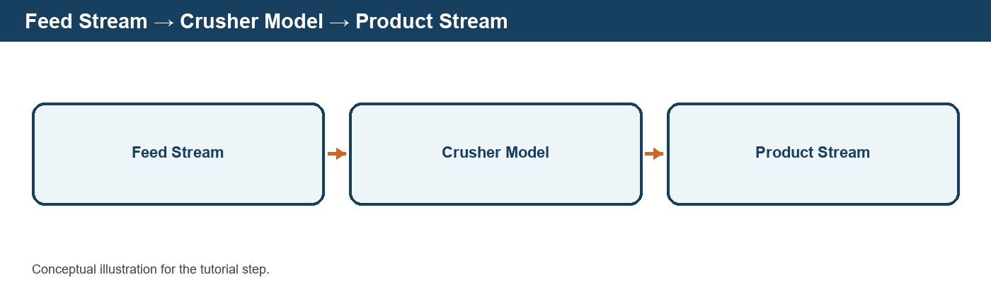
Depending on the model, some stream properties may remain unchanged while others are transformed.
A crusher primarily changes the particle size distribution.
A separator redistributes material between two products.
A thickener redistributes solids and water.
A mixer combines several incoming streams.
The same stream structure allows different unit-operation models to be connected into a complete process flowsheet.
Connecting another process unit
Add another equipment item to the right of the first process unit.
For example, add a screen after the crusher.
The flowsheet initially appears as:
Editable Feed → Crusher Screen
Now connect the crusher Product port to the screen Feed port.
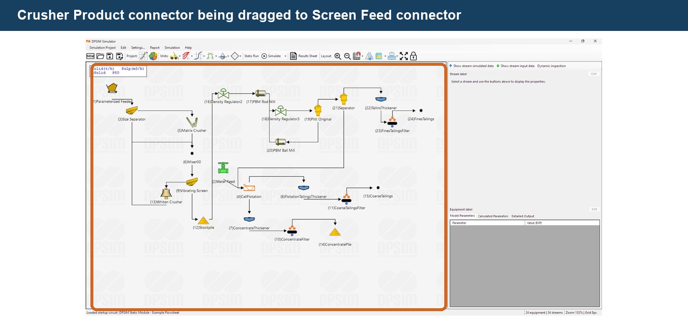
The flowsheet becomes:
Editable Feed → Crusher → Screen
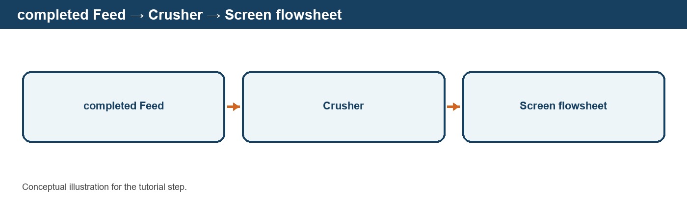
Material can now travel from the feed through the crusher and into the screen.
The process topology is beginning to resemble an actual mineral processing circuit.
Equipment with multiple outputs
Some models produce more than one process stream.
Consider a screen.
It receives one feed:
Feed
and produces two products:
Oversize
and
Undersize
Conceptually:
**→ Oversize**Feed → Screen
**→ Undersize**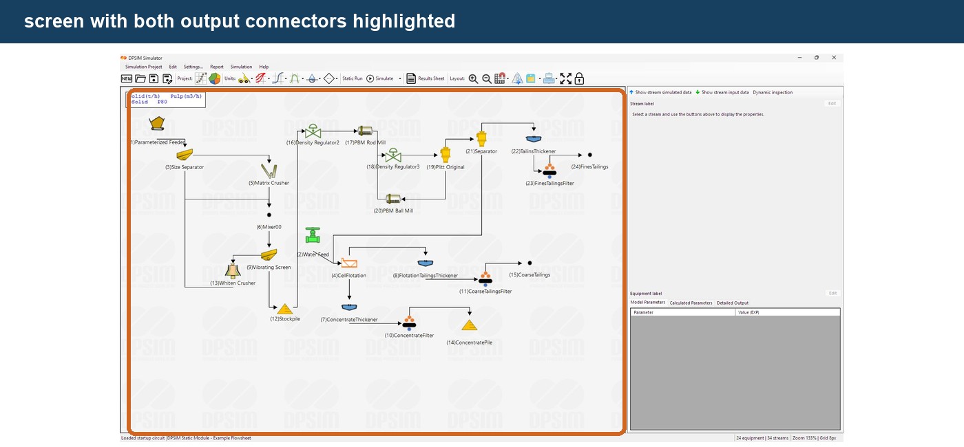
Each output port has its own stream.
The screen model determines how the incoming material is distributed between these outputs.
Once calculated, each stream can have a different:
- solids flowrate;
- water flowrate;
- PSD;
- component distribution;
- grade.
The two streams can then be connected to different downstream equipment.
For example:
Oversize → Crusher
and:
Undersize → Product
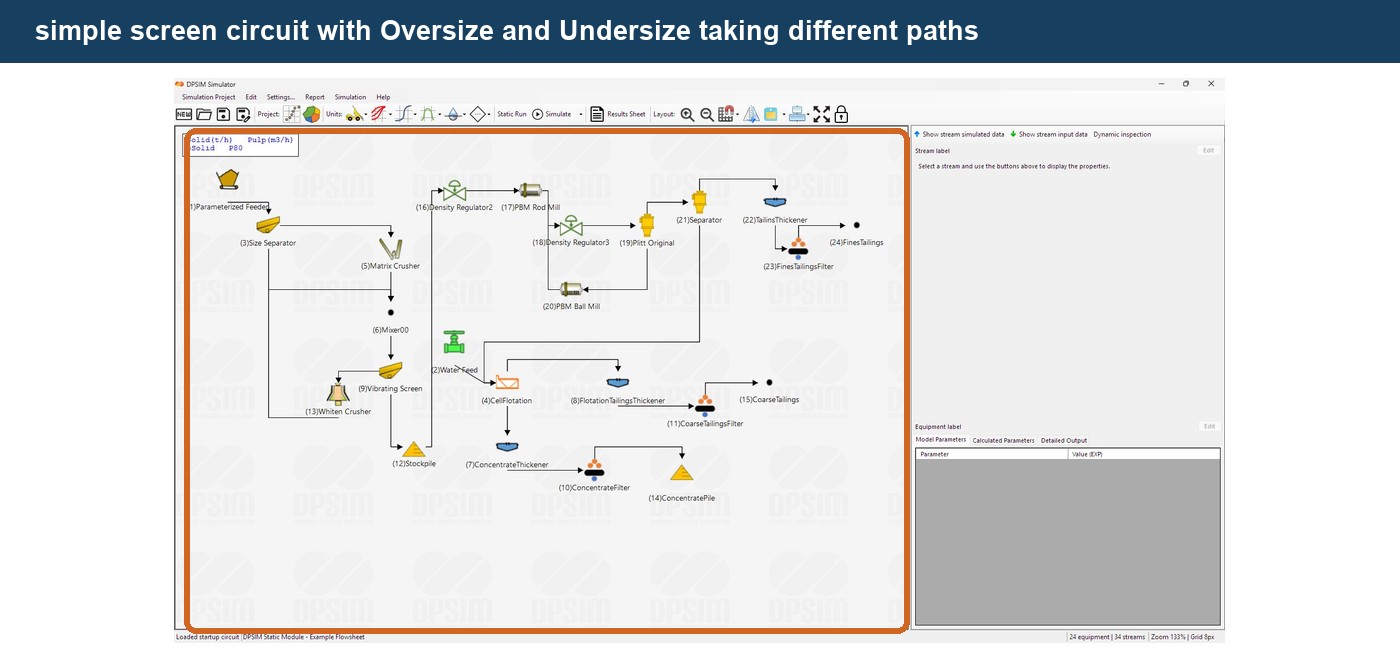
This is how branching flowsheets are constructed.
An output stream has one destination
A normal equipment output represents a single process stream.
Therefore, the same output cannot simply be connected independently to two different downstream units.
For example, this is not the correct way to represent a physical split:
**→ Equipment A**Product
**→ Equipment B**Instead, when one process stream needs to be divided between two destinations, use an appropriate Splitter model.
Conceptually:
**→ Equipment A**Product → Splitter
**→ Equipment B**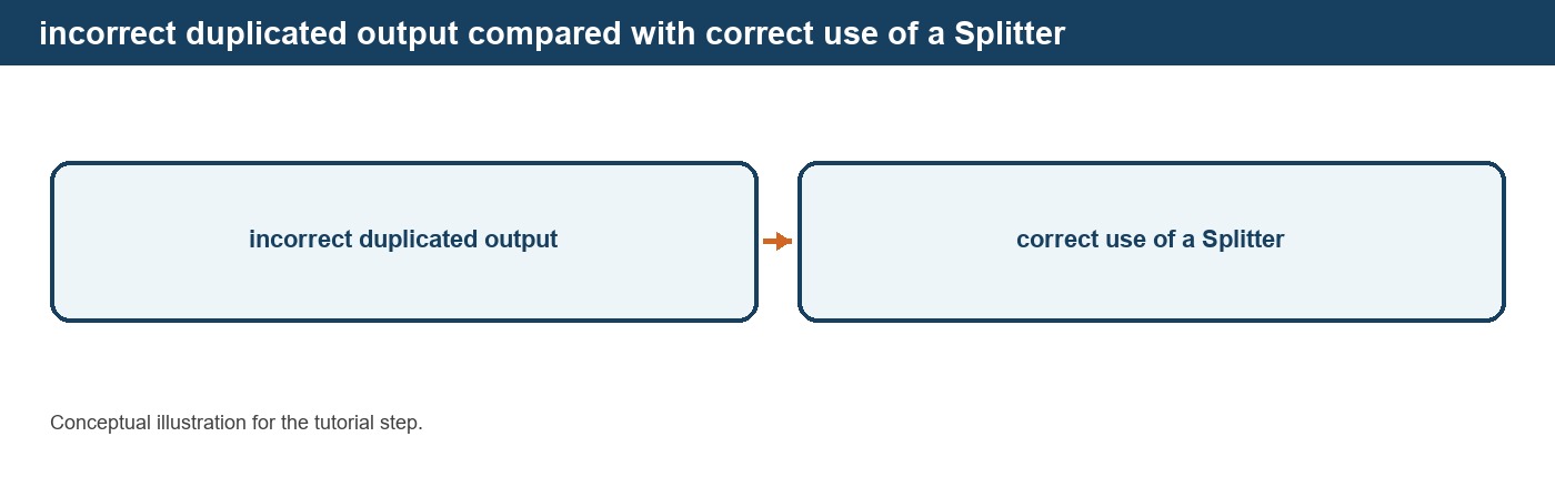
This is an important modeling principle.
A branch in the graphical flowsheet should correspond to a defined process operation that determines how the material is divided.
DPSIM also prevents a standard output stream that is already connected from being connected again to another destination.
Multiple incoming streams
The opposite situation is also common.
Two or more process streams may need to be combined.
For example:
Fresh Feed ──┐
**→ Mixer → Combined Feed**Recycle ─────┘
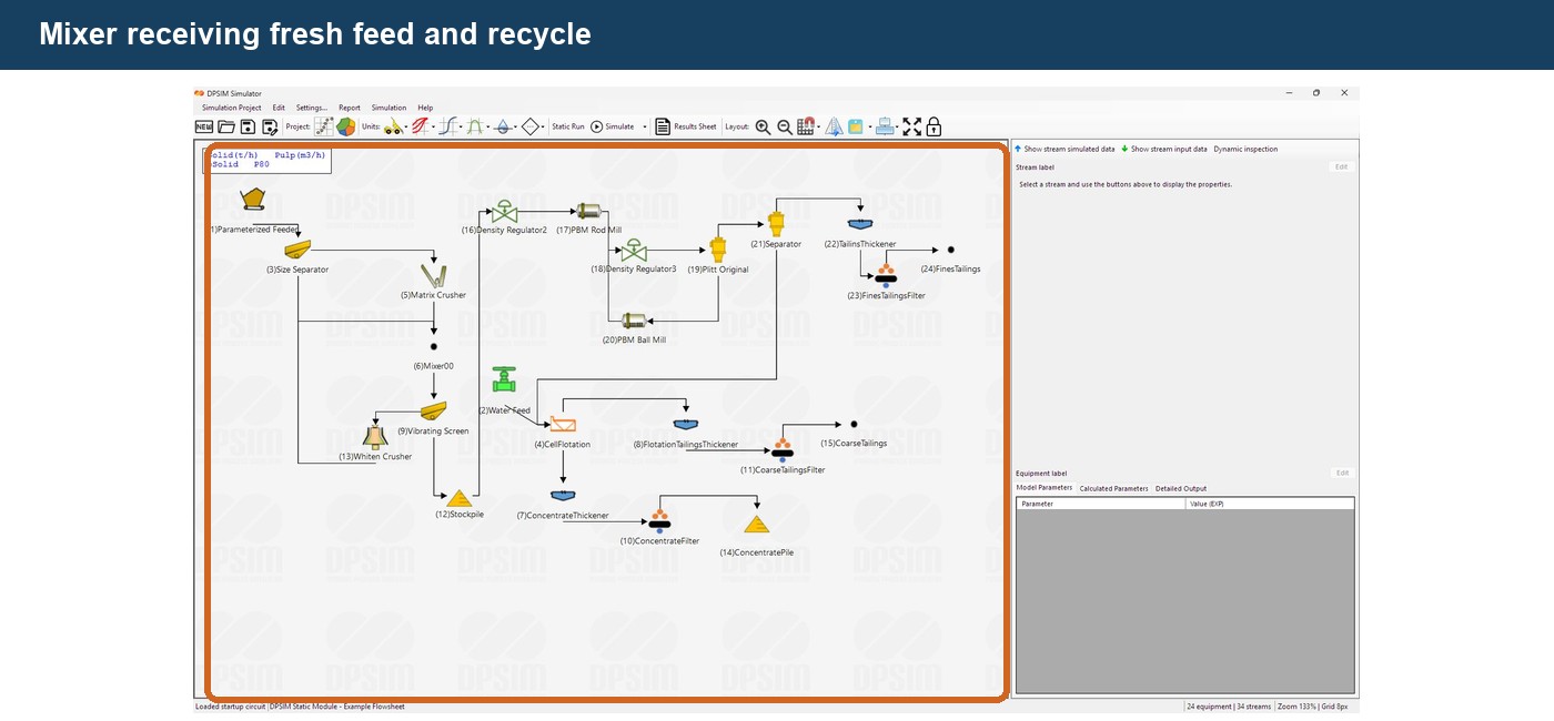
A Mixer provides an explicit process location where those streams are combined.
The resulting output stream represents the combined mass, water, PSD and component composition of the incoming streams.
This will become particularly important when we build closed grinding and crushing circuits later in the series.
Stream connectivity is stored with the project
DPSIM does not store a connection merely as a drawn line.
The project records:
- the source equipment;
- the source port;
- the destination equipment;
- the destination port.
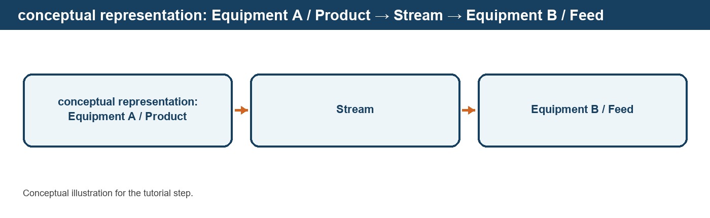
This allows the flowsheet topology to be reconstructed when the project is reopened.
The graphical stream therefore represents an actual relationship in the simulation model.
The code also preserves the port role, direction and connection information when structured project files are saved and restored.
Streams and equipment numbering
As connections are created, DPSIM manages the flowsheet stream and unit identification internally.
These identifiers help distinguish streams throughout the project and are used by simulation, reporting and export functions.
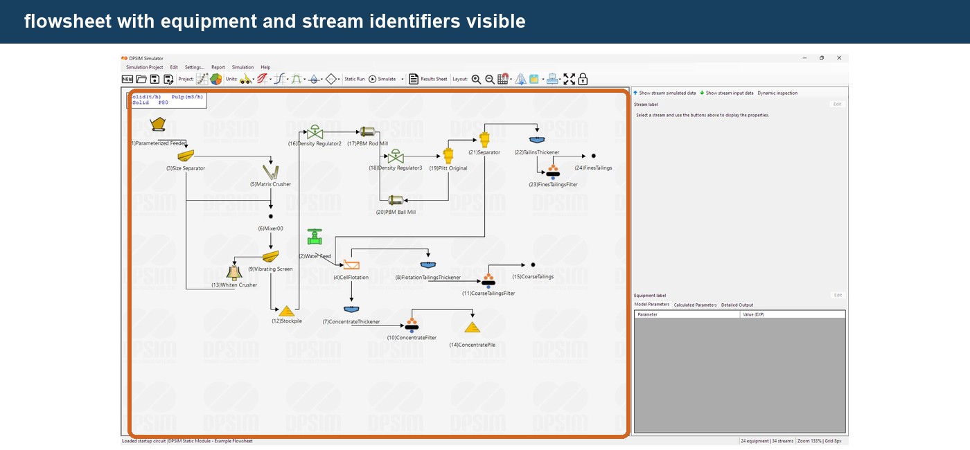
For larger flowsheets, clear equipment names remain important even when numerical identifiers are available.
A stream number tells us which stream is being referenced.
A descriptive equipment label helps us understand what the stream means in the process.
Removing or changing a connection
During flowsheet development, process connections often need to change.
A stream can be selected on the flowsheet and removed when the circuit topology needs to be modified.
The upstream and downstream equipment remain in the project, but the process relationship between them is removed.
You can then create a new connection between the appropriate ports.
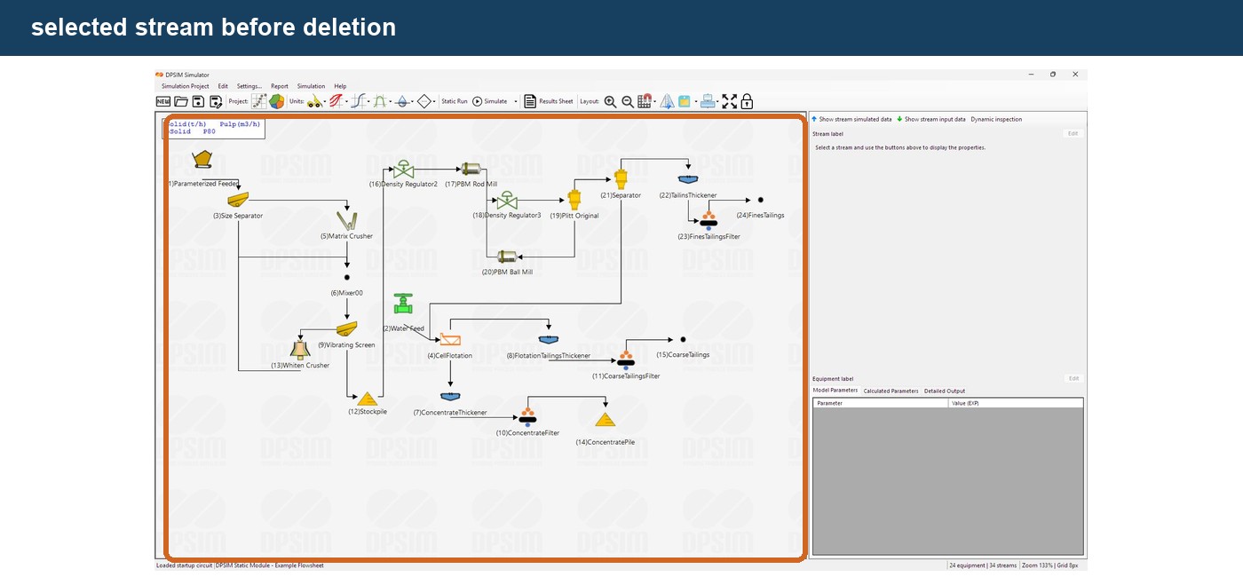
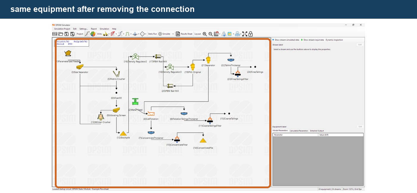
This makes it easy to test alternative flowsheet configurations without recreating every process unit.
After changing the topology, always verify that each stream reaches the intended destination.
Keep the process direction visually clear
DPSIM allows flexible equipment positioning, but a flowsheet is easier to understand when the graphical arrangement generally follows the material direction.
A useful convention is:
Feed on the left
Process units progressing toward the right
Products toward the right or bottom
Recycle streams returning clearly to upstream equipment
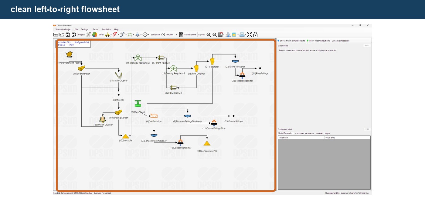
Compare this with a flowsheet where streams cross unnecessarily and equipment is positioned without following the process sequence.
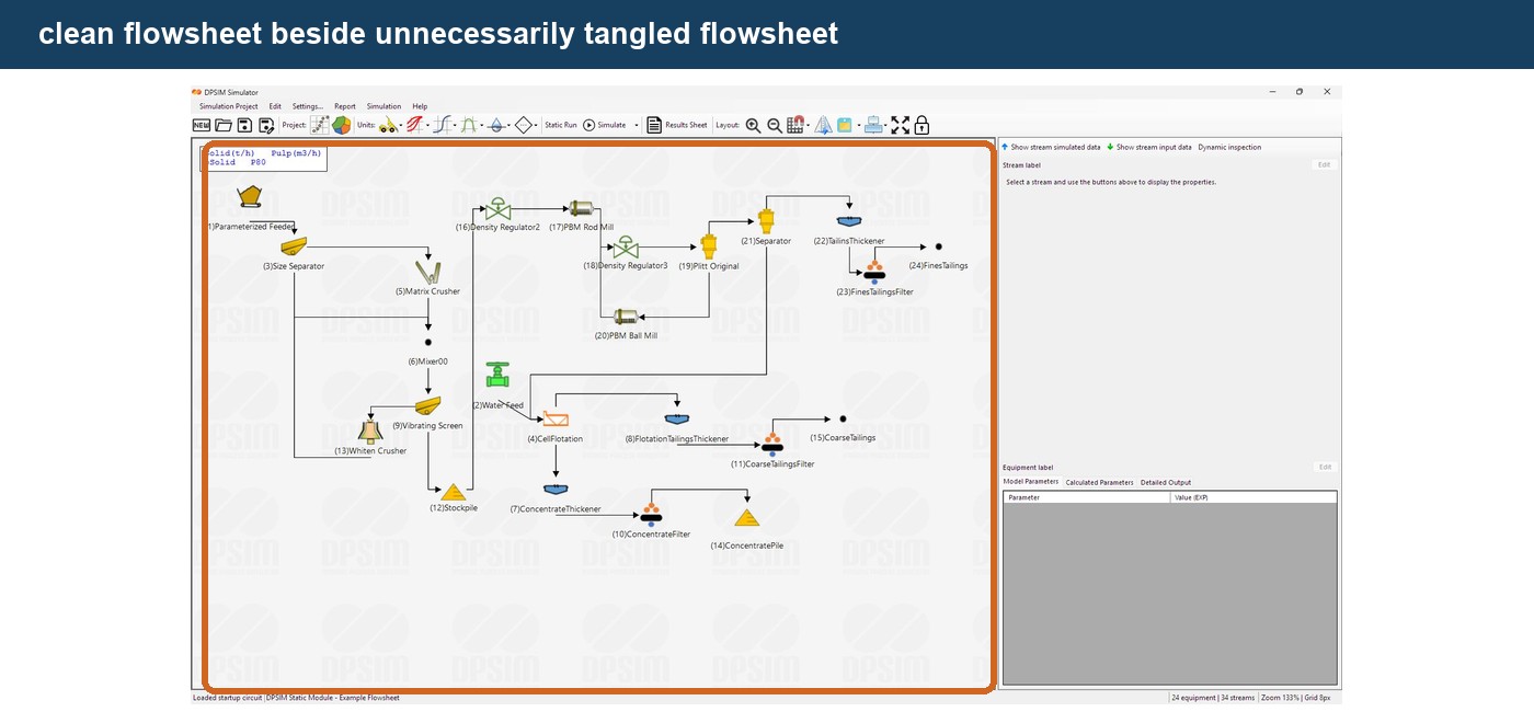
Both could represent exactly the same mathematical topology.
But the cleaner layout is much easier to:
- review;
- troubleshoot;
- present;
- modify;
- communicate to another engineer.
Engineering note
Flowsheet organization does not change the mass balance.
But it strongly affects the probability of human error when building and reviewing the model.
Good simulation practice includes making the process topology visually obvious.
Our first connected process
Using the example developed throughout this tutorial series, we can now construct:
Editable Feed → Crusher → Screen
The feed carries the material definition established earlier.
The crusher receives that material through its Feed port.
Its Product stream becomes the feed to the screen.
The screen will eventually generate Oversize and Undersize streams.
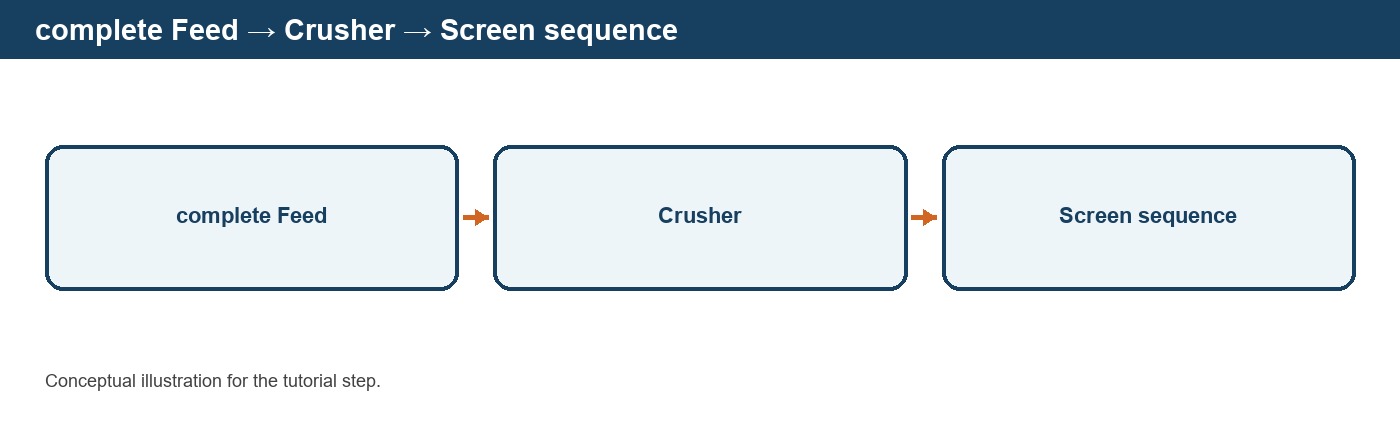
We now have the basic structure required for a process simulation:
Material
↓
Streams
↓
Process Models
↓
New Streams
This structure can be repeated to build circuits ranging from a single unit operation to a complete mineral processing plant.
From connectivity to flowsheet organization
As the circuit becomes larger, straight connections between neighboring equipment are no longer enough to keep the flowsheet readable.
Recycle streams, parallel process routes and multiple products may require streams to be routed around other equipment.
DPSIM allows additional routing points to be inserted into streams so their paths can be organized without changing the underlying process connection.
In the next tutorial, we will work with stream nodes and show how to organize complex flowsheets while preserving the same process topology.