
Developer · Tutorial
From material definitions to a process model
A connected drawing becomes a process model when its materials, quantities, equipment assumptions and starting conditions have a consistent meaning.
The material basis comes before the calculation
A material stream carries more information than a single flow value. Components describe what the material contains; size classes describe how its solids are distributed by particle size. Flow rates establish how much passes per unit of time. Equipment models use these definitions to calculate the outgoing material.
This order explains why component and size definitions come before feed distributions. A fraction has no unambiguous meaning until its component or size interval is known. The existing Static tutorials explain the shared dialogs for components, size classes and feed specification.
Equipment connects assumptions to results
An equipment item combines a selected model, input parameters and material ports. Connections describe where its outgoing streams go. A line’s appearance alone is insufficient to establish the intended relationship: the connected ports identify which material is passed to which unit.
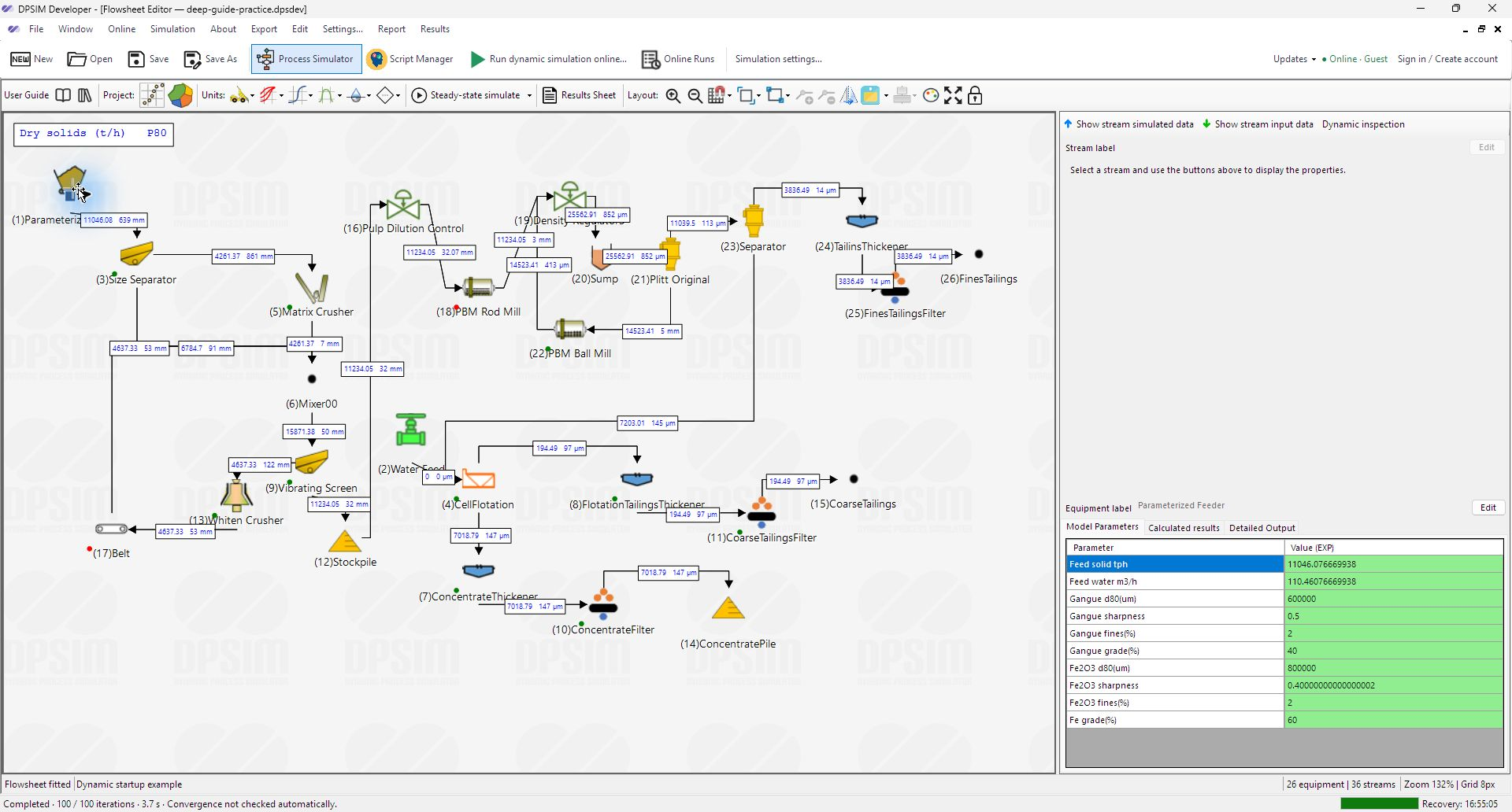
The right-hand panels follow the selected object. The stream panel describes a selected stream; the equipment panel describes a selected unit. Model Parameters are the inputs to that unit. Calculated results and Detailed Output concern what the current calculation produces. The separation is important when deciding whether a value is an assumption or a result.

A feeder illustrates the difference between quantities
The Parameterized Feeder has separate inputs for dry solids mass flow and water volume flow. In the captured interface, Feed solid tph is expressed in t/h and Feed water m3/h in m³/h. Their different units reflect different physical bases, even though both influence the material leaving the feeder.
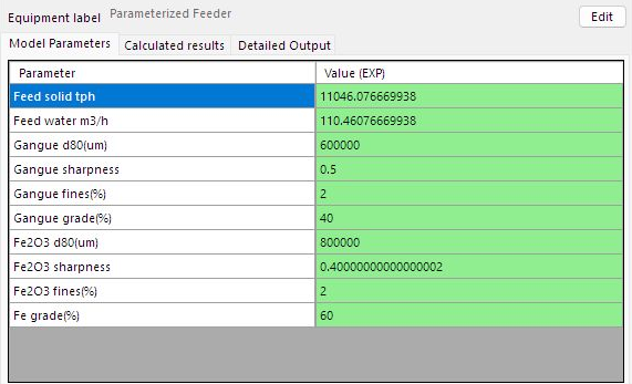
A downstream slurry mass flow cannot be obtained simply by adding those two numbers: water volume must first be related to mass through density. Similarly, a component grade, a size-distribution parameter and a total flow describe different attributes. Understanding the basis of each input is more useful than trying to make every displayed flow match.
The values visible in this saved base case are starting inputs. The ROM script has separate nominal settings and can change the commands during dynamic execution. A manually entered feeder value is therefore not necessarily constant throughout the study.
Ports explain where material moves
The Equipment properties dialog relates a model to its ports and buffer streams. Selecting a port reveals its kind, label, stream label and connection. This gives a precise way to distinguish the equipment’s own port from the upstream or downstream item connected to it.
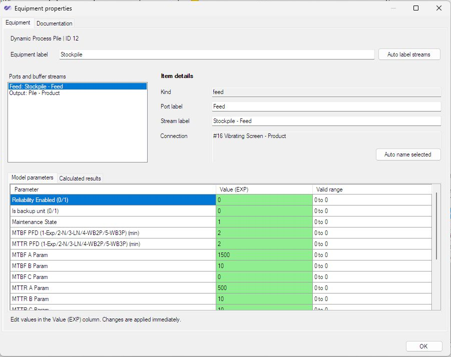
The dialog also separates model inputs from calculated results. Its notice states that input edits are applied immediately; closing the window is not an undo transaction. This is one reason the exercise begins with an independent saved copy. The model reference documents these configuration boundaries.
A dynamic model also needs a starting state
A storage unit has an amount already held before the first calculation step. This inventory differs from an entering or leaving flow: tonnes describe an amount, while t/h describes a rate. Starting empty and starting with an operating inventory are different physical experiments.
For supported storage equipment, the Initial inventory fields distinguish solids held, water held and a reference stream for solids composition and size distribution. The inventory is applied before the initial recorded sample. A nonzero mass alone is not a complete material state if its composition has not been defined. The manual documents the inventory fields and their bases.
Exercise: explain one path through the circuit
- In the saved example copy, select the Parameterized Feeder and identify its dry-solids and water inputs. Follow its outlet to the next equipment item.
- Open an equipment’s properties and select a port. Compare the listed connection with the route visible in the flowsheet. Inspect the input and calculated-result tabs without changing them.
- For the study you intend to make, write down which inputs are fixed, which will change, and which equipment starts with stored material. This description becomes the basis for the scripts.
- Where applicable, run Simulation → Run steady-state simulation and inspect selected stream outputs and balances. The calculation is local and excludes scripts and dynamic controls.
